Leakage Reactance Test Procedures
3-4 72A-2243-01 Rev. B 9/04
September 17, 2004
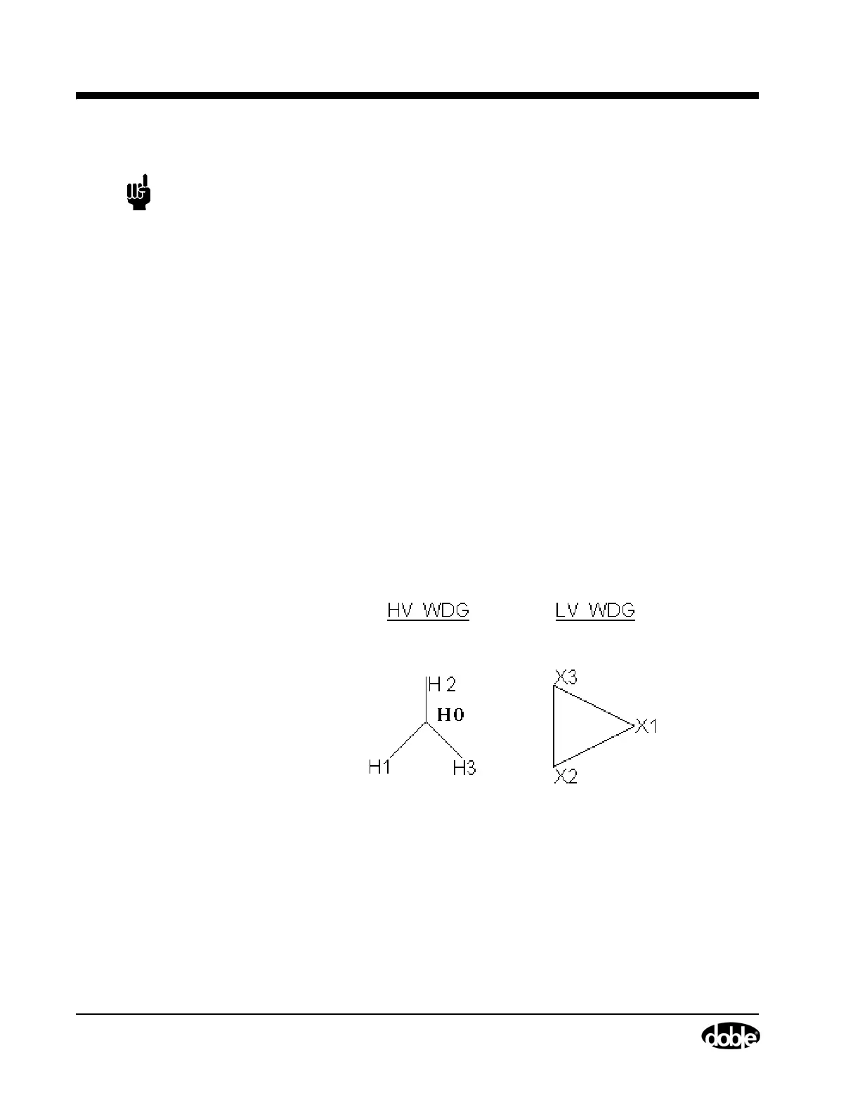
NOTE These test connections represent common transformer winding vector
relationships. Always check your transformer nameplate drawing to be
sure the phase short-circuited corresponds to the phase energized! The
consequence of short-circuiting the wrong winding will be that the tester
will not be able to obtain the recommended current to run the test. For
example, for a Per-Phase Wye test, a transformer with the following
vector representation of its winding relationship would require the
different connections shown:
Figure 3.1 Example of Transformer Winding Vector Diagram Requiring
Modified Leakage Reactance Test Connections
Test Procedures for a Two-winding Three-Phase Unit
With the M4000 insulation analyzer, which uses single-phase excitation, the
leakage reactance of a three-phase unit can be measured using two methods:
the three-phase-equivalent test and the per-phase test.
Table 3.1 Example of Modified Connections for Leakage Reactance
Per-Phase Wye Test
Connections Shown In
Manual For Per-Phase Wye
Test
Connections Required by
Per-Phase Wye Test For
Wye-Delta Vector Diagram
Shown Below
Energize Short Energize Short
H1-H0 X1-X3 H1-H0 X2-X1
H2-H0 X2-X1 H2-H0 X3-X2
H3-H0 X3-X2 H3-H0 X1-X3