INPUT,
OUTPUT,
AND ALL
THOSE
FUNKY
BUTTONS
.
1
4
5
6
7
8
9
10
2
3
11
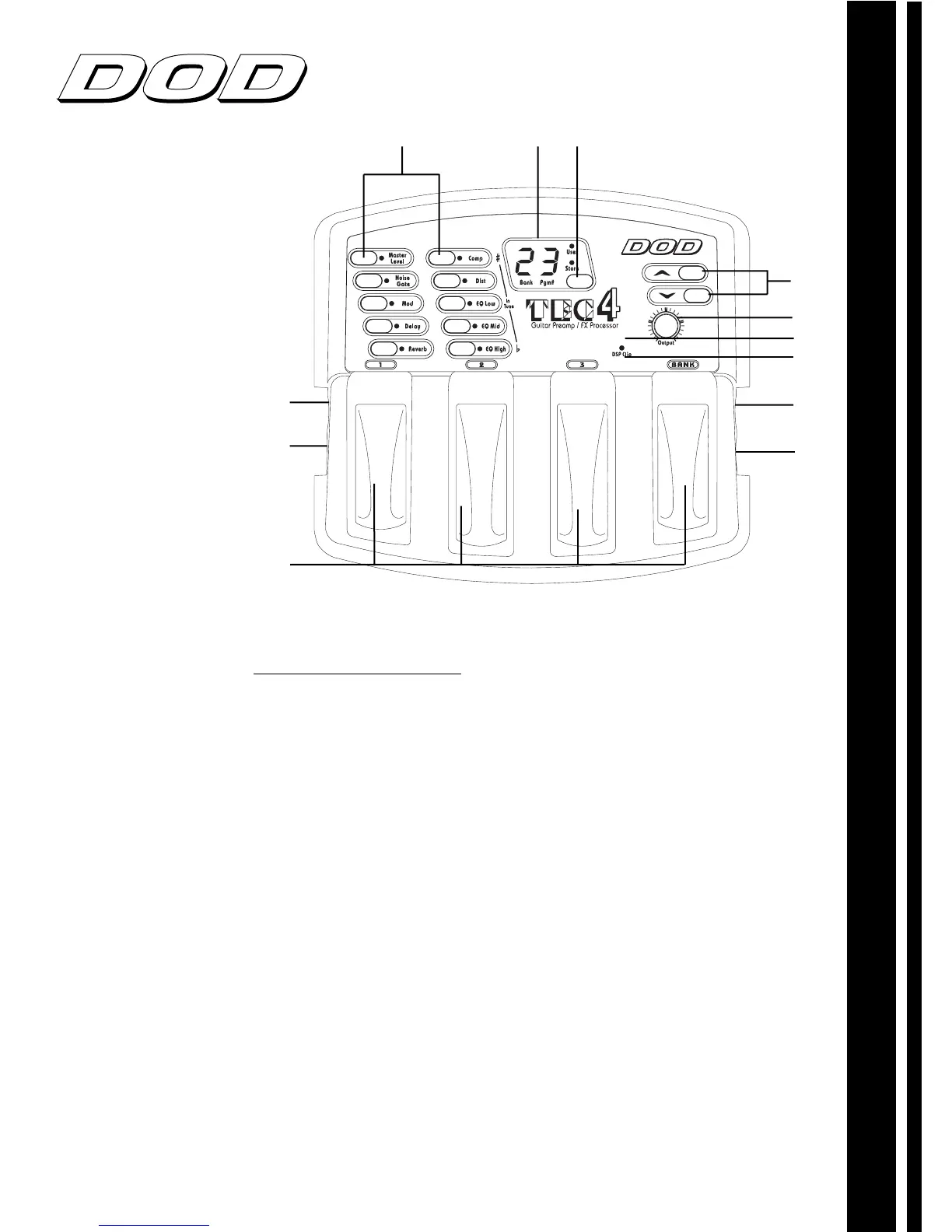
1. Program and bank selector footswitches
These
footswitches provide access to the AcousTEC’s banks/programs.
2. Power adaptor input
This is where the DOD PS200R power
supply is connected. Use only the DOD PS200R, other
adaptors may damage the AcousTEC, and void the warranty.
3. Controller
Connect
optional
DOD VCC1 to have real time control
over volume levels
4. Effect selector buttons
These buttons allow you to select the
effects you wish to use or bypass.
5. Display
The LED display in program mode shows which bank
and program is currently selected. In Edit mode it shows the
number and/or status of the selected effect. In Tuner mode it
displays the note currently being played.
6. Store Button
Use this button to store your custom programs in
the user memory location of choice.
7. Up/Down buttons
These buttons scroll up/down selected
effects (edit mode), or up/down through banks/presets
(performance mode).
8. Input Knob
Controls the input level from your guitar input.
9. Digital Notch Filter
Attenuates selected frequencies in order to
control feedback.
10. Clip LED
The clip LED lights when clipping occurs at the input
of the AcousTEC, To eliminate clipping, reduce the setting of
your guitar level, or adjust input knob. Allow the LED to light
occasionally with peak signals.
11. Output jack
Connect cable from this jack to your amplifier input,
also doubles as headphone output.
12. Input jack
Plug in your instrument here.
AcousTEC OWNERÕS MANUAL
MULTI EFFECTS PROCESSING
12
 Loading...