1
FEATURES
• 120VACInput50/60Hz
• FullWave90VDCOutput
• 0.80AmpRating
• SwitchProtection
• Operatesaclutchorbrake
SPECIFICATIONS
INPUT:120VAC,50/60Hz,1phase,100VAMax.
OUTPUT:90VDCnominal,fullwaverectied,0.80ampsMax.
AMBIENTTEMPERATURE:–40°F(–40°C)to122°F(50°C)
SWITCHING:Suppliedbycustomer.
1. Electromechanical:
Singlepolesinglethrow,rated120VAC,1ampmin.
2. Solidstate:
Triac,rated120VAC,1ampmin.(offstateleakagecurrent
at2mAMax.)
WARNING: Because of the possible danger to person(s) or
property from accidents which may result from the improper
use of products, it is important that correct procedures be
followed: Products must be used in accordance with the
engineering information specified in the catalog. Proper
installation, maintenance and operation procedures must
be observed. The instructions in the instruction manuals
must be followed. Inspections should be made as necessary
to assure safe operation under prevailing conditions. Proper
guards and other suitable safety devices or procedures as
may be desirable or as may be specified in safety codes
should be provided, and are neither provided by Baldor
Electric Company nor are the responsibility of Baldor
Electric Company. This unit and its associated equipment
must be installed, adjusted and maintained by qualified
personnel who are familiar with the construction and
operation of all equipment in the system and the potential
hazards involved. When risk to persons or property may be
involved, a holding device must be an integral part of the
driven equipment beyond the speed reducer output shaft.
Instruction Manual for Dodge Model 50
Clutch/Brake Power Supplies
Theseinstructionsmustbereadthoroughlybeforeinstallingoroperatingthisproduct.
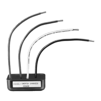
DESCRIPTION
TheModel50Clutch/Brakepowersupplyiscapableofoperating
any DODGE clutch orbrake within its rating. Switching for the
DODGE Model 50 is done on the 120 VAC input of the power
supplyviaacustomersuppliedswitch.Internalcircuitryprovides
suppression of switching transients thus ensuring both fast
responseandswitchprotection.
INSTALLATION
1. MOUNTING:
TheModel50powersupplymaybemountedinanyconvenient
locationusingthemountingdimensionsshowninFigure1.
1.070
2.140
.625
.570
1.140
WIRE LEADS ARE
6” LONG
.171 DIA FOR
#8 SCREW
Figure 1 - Mounting of Model 50 Power Supply
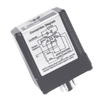
2. WIRING:
Connections to the power source, switch and clutch or brake
coilsasperFigure2.
Clutch/Brake Connections: Before connecting the lead wires
fromtheclutchorbrake,measurethecoilresistancetoensure
itisatleast112ohms.Iftwoclutchesorbrakesareusedona
singleoutput,theequivalentparalleltotalresistancemustexceed
112ohms.Thiswillmakesurethepowersupplywillhandlethe
amperagerequired.Thewiresizeformakingconnectionsshould
be consistent with current ratings of the clutch and brakeand
lengthofwirebetweenthepowersupply,switch,clutchorbrake.
WARNING: The user is responsible for conforming to the
National Electrical Code and all other applicable local codes
in respect to wiring practices, grounding, disconnects,
and overcurrent protection. Installation of an approved
disconnecting means in the line side of the controller is of
particular importance. Failure to observe these precautions
could result in severe bodily injury or loss of life.