A-123
VCF 4
System A - 100
doepfer
4
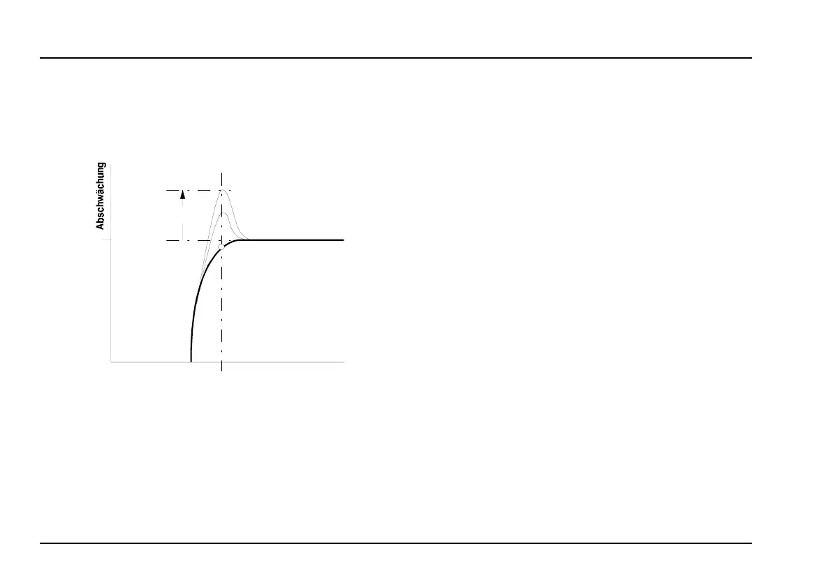
At close to maximum resonance, the filter starts to
self-oscillate, and behaves like a sine wave oscilla-
tor. Thanks to this effect, you can use the filter as an
independent tone source.
Fig. 2: How resonance affects the behaviour of a
high pass filter.
4. In / Outputs
! Audio In
This is the filter’s audio input socket, where you
patch in the output from any sound source.
" FCV 1
Socket FCV 1 is a voltage control input for the filter.
It works on the 1V / octave rule, like the VCOs.
If you connect the output of a modulation source (eg
LFO, ADSR) to this input, the cut-off frequency of the
filter will be modulated by its voltage: ie, the sound
color changes according to the voltage put out by the
modulator.
P If you use this VCF as a sine wave oscillator,
connect a pitch control voltage to this input.
Do the same if you want the filter’s cut-off
frequency to track exactly with the pitch of a
note.
§
FCV 2
Socket
§
is also a voltage-control input for the filter.
Unlike on socket
"
, though, you can adjust the level of
voltage by using the attenuator
3
, and thus control the
intensity of modulation effect on the filter.
f
c
Resonanz
Frequenz
0 db
 Loading...

