A-123
VCF 4
System A - 100
doepfer
6
24 dB notch filter with voltage control of
middle frequency and bandwidth
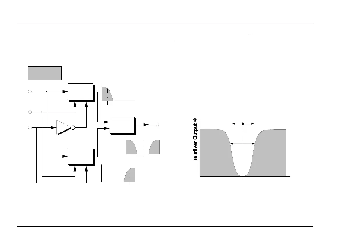
The patch in Fig. 3 shows a 24 dB notch filter with
voltage-controlled middle frequency and bandwidth.
Fig. 3: 24 dB notch filter with voltage control of
middle frequency and bandwidth.
For this patch, set both f
L
(L ow Pass A-122) and f
H
(H igh Pass A-123) to roughly equal cut-off points
(judging by ear).
Use a control voltage "FCV" to alter the middle fre-
quency f
M
of the notch filter: f
M
= (f
L
+ f
H
) / 2.
Use a control voltage "BCV" to alter the bandwidth,
which is determined by how far apart the two filters’
cut-off frequencies are. Using the A-175 Voltage
Inverter, these frequencies
f
L
and
f
H
are altered sym-
metrically around the middle frequency (see Fig. 4).
Fig. 4: Effect of FCV and BCV on the notch filter’s
response.
f
H
Freq.
Ö
A-122
Freq.
Ö
A-123
Freq.
Ö
f
L
A-138
Freq.
Ö
f
M
A-175
Audio
In
FCV
BCV
Audio
Out
CV 1 CV 2
CV 1 CV 2
Freq.
Ö
FCV
BCV
f
M
 Loading...