3. A-100 signal flow System A - 100
doepfer
8
As well as modules which can be affected by voltage
control, there are other modules like the ADSR and
LFO which themselves produce voltages to control
other modules.
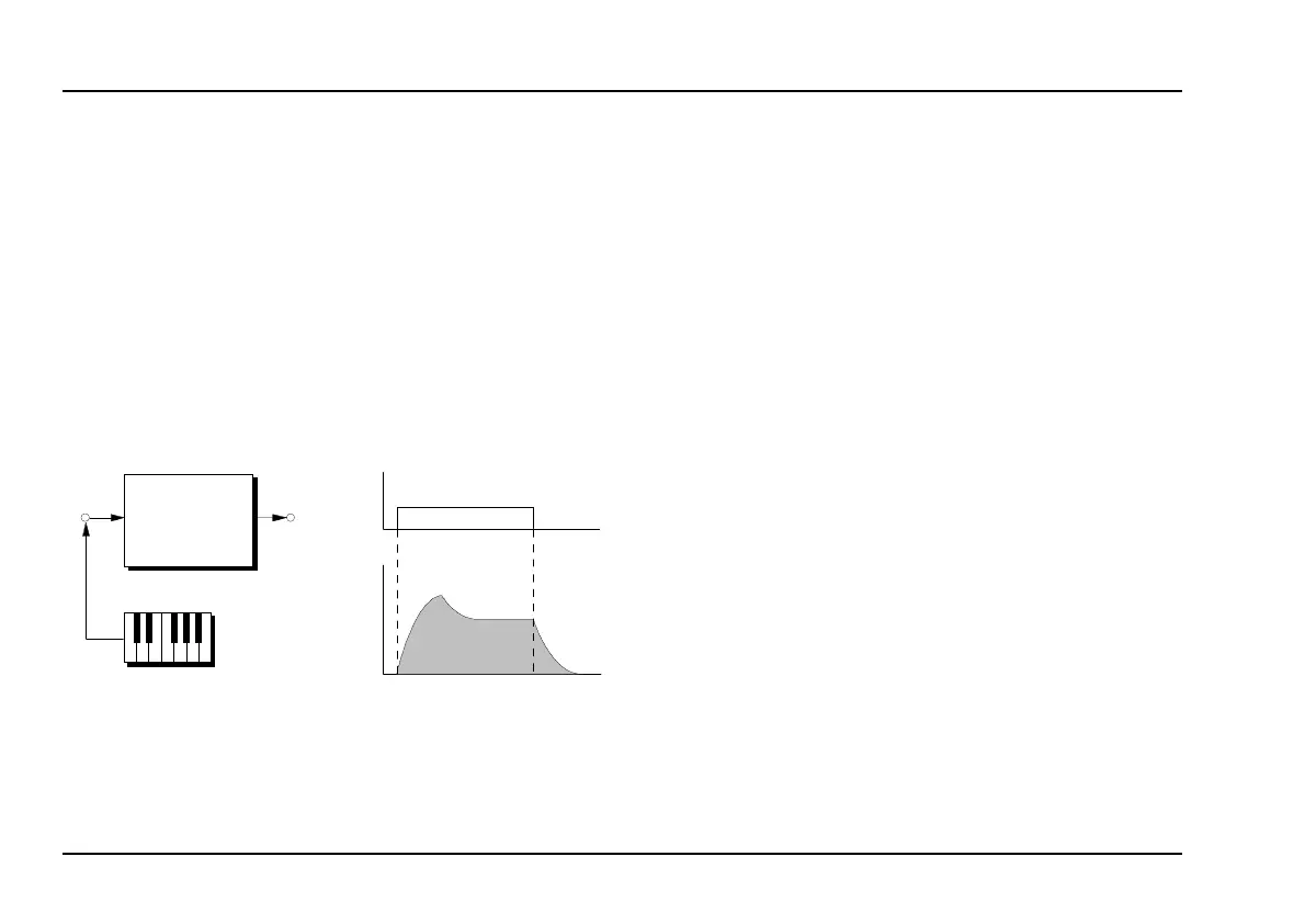
Usually, these modules need a Trigger Signal to bring
them into action. For instance, a GATE Signal, corre-
sponding to a key being pressed on a keyboard, can
set off an ADSR, which then puts out its variable
voltage “envelope” to affect other modules (see Fig.
6).
Fig. 6: The envelope generated by an ADSR
3.2 Signals in the A-100
In the System A-100 there are three types of signal:
• Audio Signals
• Control voltages
• Trigger voltages
Audio Signals are produced by the sound source
Modules (such as VCO or NOISE), and lie in the range
from -5 V to +5 V (10 V
SS
). The System A-100 can also
let you use external Audio Signals (e.g. Microphone,
Electric Guitar, Keyboard).
H
To interface satisfactorily, the level of exter-
nal Audio Signals must be brought up to the
A-100’s operating level.
Module A-119 (External Input), is ideal for
this job, having among other things an inter-
nal pre-amp, and two inputs of different sen-
sitivity.
Control voltages, as produced by modulation sources
like the LFO and ADSR, are typically from -2.5 V to
+2.5 V (5 V
SS
) for the LFO, and from 0 V to +8 V for
the ADSR.
+ 5 V
0 V
On
Off
t
GATE
CV Out
ADSR
t
CV Out
GATE