A-147
VCLFO
System A - 100
doepfer
4
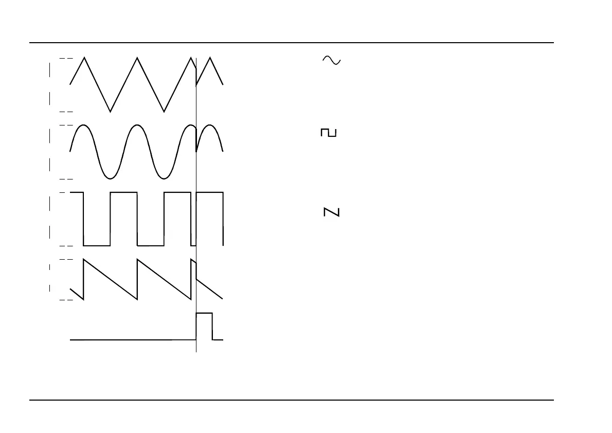
Fig. 1: How sync affects the waveforms
$
This socket outputs a sine wave (amplitude range
roughly
±
5 V), whose frequency / voltage state is
indicated by LED
3
.
%
This socket outputs a
square wave
(amplitude roughly
± 5 V), whose frequency / voltage state is indicated by
LED 4.
&
This socket outputs a
falling sawtooth wave
(amplitude roughly +7 V) whose frequency / voltage
state is indicated by LED 5.
H In contrast to the A-145 standard LFO, the
sawtooth is the identical frequency to the
other waveforms (while the A-145 sawtooth
is double the others’ frequency).
~ +5 V
~ -5 V
~ +5 V
~ -5 V
~ +5 V
~ -5 V
~ +7 V
0 V
➌
➍
➎
➏
➊
Gate
Reset
Reset
 Loading...