doepfer
System A - 100
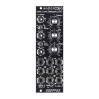
VCLFO A-147
3
3. Controls and indicators
1 Frequ.
This control sets the frequency of the VCLFO in a
range from 0.01 Hz (one cycle every 100 seconds) to
50 Hz (50 cycles a second).
H The actual LFO frequency is determined by a
combination of manual control and any vol-
tage patched into CV input
"
.
2 CV
Use Attenuator
2
to set the level of the voltage at CV
input " affecting the VCLFO frequency.
3 LED ... 5 LED
LEDs
3
to
5
indicate the frequency and voltage state
of the LFO signals at their respective outputs.
H If the LFO frequency is higher than about 15
to 20 Hz, our persistence of vision means
that the LEDs look permanently on.
4. In- / Outputs
! Reset
A gate pulse entering the
reset input socket
!
enab-
les the VCLFO to be synchronised with another
oscillator.
This means that the waveforms instantly go to their
zero-point, and start from there (see Fig. 1). In the
case of the triangle and sine waves, that’s 0 V; with
the square wave it’s about +5 V and the sawtooth it’s
at half its maximum (about +3.5 V).
" CV
Socket
"
is the
voltage control input
for LFO fre-
quency. The voltage at this input is added to whatever
voltage is set on the manual control 1. The level of CV
input
"
can be adjusted with the Attenuator
2
.
§
This socket outputs a triangle wave, whose frequency
is indicated by LED 3 (amplitude roughly ± 5 V).
 Loading...