Solar Pump Inverter Chapter 3 System Collection Diagram
16
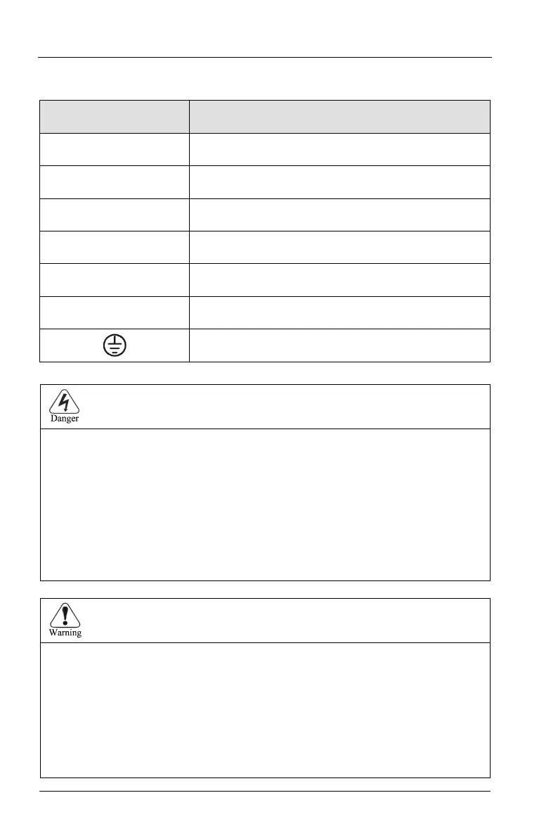
3.1.2 Instructions of Main Circuit Terminals of Inverter:
Terminal Description
R、S、T Terminals of 3 phase AC input
(+)、(-)
Terminals of 2 phase DC input
(+)、PB Spare terminals of external braking resistor
P1、(+) Spare terminals of external DC reactor
(-)
Terminal of negative DC bus
U、V、W Terminals of 3 phase AC output
Terminal of ground
● the voltage class of CT112 series inverter 3phase power has 2 class: 220V, 380V,
before connecting power, please make sure the power class on inverter nameplate is
the same with the accessing power. Otherwise do not connect.
● DC bus (+) (-)terminal: take note that when power outrage there is residual voltage on
DC bus P+ P- terminal, need to wait for a while until CHARGE LED off. Otherwise it is
danger of electric shock.
●When selecting external brake unit, note the polarity of P= (+) and (-) cannot be
reversely connected, otherwise it can result in damage or even fire.
Do not directly connect brake resistor to DC bus, it may result damage or fire.
1)Input power L,N or R, S T: the cable connection at input side of the inverter has no
phase sequence requirement.
2)Brake unit cable length should not exceed 10m, twisted pair or double cable parallel
wiring should be used.
3)Brake resistor connecting terminal (+) (-): confirm whether the device has built-in
brake unit, its brake resistor connecting terminal is effect. The brake resistor selection
table 2-4 recommending value and the wiring distance should less than 5M.
Other it can damage inverter.