EasyManua.ls Logo

domat UC120 User Manual

domat UC120
7 pages
To Next Page IconTo Next Page
Page #1 background imageLoading...
Page #1 background image
domat UC120 03/2017 Subject to technical changes. 1
UC120
Communicative heating
controller, 0..10 V output
Summary
UC120 is a communicative room heating controller with one binary input and one
0...10 V DC output for control of a radiator or electrical heater. It can work
autonomously, or in connection to a primary controller (MiniPLC or SoftPLC), or
building management system (RcWare Vision or any SCADA).
Application
Systems with radiators, electric heaters, or floor heating control and
measuring of room temperature
monitoring and communication of room temperatures
Function
The controller reads actual room temperature, setpoint shift by a knob, and set
operation status which is set by short push of the knob. The room temperature is
measured in the range of -20 to +50 °C. Measured and set values are processed in a PI
algorithm, brought to one 0..10 V DC output. All values are displayed on a large LCD
display.
The functionality and control parameters, i.e. P and I constants, and hysteresis, can be
set with ModComTool, the configuration software, which is free to download at
http://domat-int.com/en/downloads/software.
The controller contains real time clock with a weekly scheduler (6 events per day). It
changes between three operation modes: Day, Night, and Off. A short push in the Night
mode switches to Party mode Comfort extension by 2 hours.
The Change-over function (communicated over the bus) switches to the cooling mode
while cooling setpoints come into effect. This mode is used when heat pumps with
change-over mode are installed. The change-over signal is read from the heat pump
interface or a thermostat at the supply water piping, and is transmitted to the
controllers over MiniPLC, UCWEB, or any Modbus master. See Room units and
controllers, Communication protocol description handbook for register addressing and
communication examples.
Question and Answer IconNeed help?

Do you have a question about the domat UC120 and is the answer not in the manual?

domat UC120 Specifications

General IconGeneral
CommunicationModbus RTU
Power Supply24 V AC/DC
Digital Inputs2
Analog Inputs2x, 0..10 V, 0..20 mA, Pt1000, Ni1000
Digital Outputs2 (relay)
DisplayLCD with backlight
Relative Humiditynon-condensing

Summary

Product Summary

Application Scenarios

System Control and Measurement

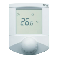
Manages heating systems and monitors room temperature.

Room Temperature Monitoring

Facilitates remote monitoring of room temperatures.

Controller Functionality

Technical Specifications

Terminal Connections

Presence Input Terminal

Terminal DI1 for presence input, active when connected to G0.

NC Terminal 1

Unused terminal (NC).

Heating Output Terminal

Terminal A01 providing a 0-10 V DC output for heating control.

Power Reference Terminal

Terminal G0 serves as a common reference point for power and output signals.

NC Terminal 2

Unused terminal (NC).

Power Reference Terminal (G0)

Terminal G0 serves as a common reference point for power and output signals.

Power Plus Terminal

Terminal G providing the positive power supply.

RS485 Communication (K-)

Negative terminal for RS485 Modbus RTU communication bus.

RS485 Communication (K+)

Positive terminal for RS485 Modbus RTU communication bus.

DIP Switch Configuration

Bus Termination (BUS END)

Configures bus termination for the last device on the line.

Reserved User Switch (USR)

Switch reserved for future application use.

Initialization (INIT)

Resets controller to default state, setting bus address and baud rate.

Installation Guidelines

Opening the Display Cover

Controller Operation

Temperature Setpoint Correction

Adjusting the room temperature setpoint using the device knob.

Operation Mode Switching

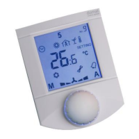
Changing between Party, Day, Night, Off, and Auto modes.

Time Schedule Configuration

Setting up daily schedules for different operation modes via the controller.

Setpoint and Time Adjustment

Modifying setpoints for various modes and adjusting the device's internal clock.

Device Dimensions

Connection and Wiring

Temperature Compensation

RoHS Compliance and Disposal

Version History

Related product manuals