Do you have a question about the Dometic 59516.601 and is the answer not in the manual?
Details the air conditioner's design, installation context, and factors affecting its temperature control.
Explains condensation phenomena and the unit's role in moisture removal during operation.
Highlights risks of improper installation, alteration, or service causing injury or property damage.
Describes the operator interface, its display, modes, fan speeds, and temperature setpoint adjustments.
Details the internal box's relays for fan, compressor, furnace, and connections for sensors and EMS.
Steps to operate the air conditioner solely in fan mode, including power and mode selection.
Procedure for activating cooling mode, compressor engagement, and fan cycling based on setpoint.
Instructions for operating the unit in furnace mode, including temperature control and fan behavior.
Guide for using the heat strip mode, fan operation, and selectable speeds in this mode.
Details on Auto Fan, compressor time delay, power interruption restart, and multi-zone operation.
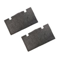
Instructions for cleaning or replacing the return air filter to maintain unit performance.
Steps to diagnose why the unit fails to operate before calling a service center.
Required information to provide when contacting a service center for assistance.
Guidance on positioning the air conditioner for a single-unit RV installation.
Recommendations for placing two air conditioners in an RV for optimal coverage.
Specifies requirements for duct depth, width, length, register size, and free area for air distribution.
Details insulation (R-7 min.) and sealing needs for ducts to prevent condensation.
Covers minimum return air opening size and acceptable total system pressure ranges.
Detailed steps for cutting a 14x14 opening and framing it for wiring and ducting.
Instructions for routing power supply, 12 VDC, remote sensor, and thermostat wires to the opening.
Guidelines for selecting an appropriate location for the Comfort Control Center in the RV.
Procedure for routing and terminating the 4-conductor telephone cable for the control system.
Steps for installing air distribution ducts in the RV roof cavity per system requirements.
Instructions on safely removing the unit from packaging and placing it onto the prepared roof opening.
Steps to prepare the divider plate based on ceiling-to-roof thickness measurements.
Procedure for attaching the divider plate using adhesive tape and securing insulation.
Details on terminating telephone cables and connecting the electronic control box components.
Instructions for installing the freeze control sensor onto the evaporator coil for 579/590 series.
Specific instructions for installing the freeze control sensor on the 600 series evaporator coil.
Guidance on connecting remote sensor and 12 VDC wires to the electronic control box.
Instructions for adjusting dip switches on the control box for system configuration.
Steps for connecting the main power supply to the electronic control box junction box.
Ensuring all installed features and operations are functioning correctly after installation.
Steps to perform system configuration by using the UP and DOWN buttons on the control center.
Instructions for attaching the return air cover to the ceiling template and reinstalling the grille.
| Brand | Dometic |
|---|---|
| Model | 59516.601 |
| Category | Air Conditioner |
| Language | English |


 Loading...