Do you have a question about the Dometic 59516.731 and is the answer not in the manual?
Symbol for safety alerts and precautions to watch for in the manual.
Explains the meaning of WARNING, CAUTION, and CAUTION signal words.
Specifications are subject to change without notice.
Details RV installation and roof construction requirements.
Measures to reduce heat gain and improve performance.
Manufacturer not responsible for damage from condensed moisture.
Improper installation can cause severe injury or property damage.
Compliance with electrical and local codes is mandatory.
Use only Dometic-authorized accessories and qualified personnel for service.
Factors to consider for cooling requirements and location.
Describes mounting placement for single and multiple units.
Installer responsibility for roof integrity and preventing water collection.
Requirements for duct material, insulation, sealing, and return air.
Installer responsibility for preventing duct collapse and ceiling damage.
Recommends configuration and installer's responsibility for RV floor plan review.
Alternate methods require Dometic approval in writing.
Disconnect power to avoid shock hazard during installation.
Instructions for cutting roof and ceiling openings.
Instructions for routing AC power supply line and circuit protection.
Installing ducts and meeting system requirements.
Guidelines for proper placement of CCC and sensor.
Specifies cable type, connectors, and termination for control cable.
Instructions for routing power, control, sensor, EMS, and furnace wires.
Unpacking, lifting with hoist, positioning, and preventing gasket damage during roof installation.
Installing ducts in the RV roof cavity.
Instructions for installing freeze control sensor for specific models.
Instructions for installing freeze control sensor for 600/630 series.
Instructions for pulling the unit electrical cord.
Disconnect power and ensure proper grounding/polarity.
Connecting AC power supply wires and ensuring secure connections.
Instructions for connecting low voltage wires from the AC unit.
Disconnect 12 VDC to prevent equipment damage.
Steps for mounting the CCC base plate and connecting the control cable.
Instructions for checking gasket alignment and preparing the ceiling template.
Instructions for installing the foam divider in the opening.
Positioning the electrical box and connecting control wires.
Tightening bolts for gasket seal, cautions on tightness.
Instructions for preparing and installing the divider plate.
Mounting electronic control box and securing ceiling template.
Warning about bolt tightness affecting roof seal or template damage.
Sealing divider plate to base pan, caution on effectiveness, applying insulation.
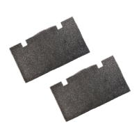
Sealing foam divider ends and installing decorative cover with wiring.
Securing control box, installing cover, and reinstalling filter grill.
Inserting filter, placing grill, and installing slide handle.
Setting dip switches, tool usage, and adjustment for zones, heat strip, sensor, furnace, and differential.
Performing system reset after configuration and verifying all system features.
Wiring diagram for the air conditioner unit.
Wiring diagram specific to Penguin models.
Wiring diagram specific to Brisk Air models.
| Brand | Dometic |
|---|---|
| Model | 59516.731 |
| Category | Air Conditioner |
| Language | English |