Do you have a question about the Dometic DDC and is the answer not in the manual?
Lists key hardware and software upgrades enhancing performance and reliability.
Explains the DDC module's function in modular chiller assemblies for temperature control.
Details the various sensors and switches that provide data to the DDC module.
Details the compressor output specifications for 230 VAC and 115 VAC systems.
Specifies the chillwater pump operation and its amp ratings for 230/115 VAC.
Outlines seawater pump operation tied to compressor status and its amp ratings.
Explains reversing valve operation for heating/cooling and head pressure relief.
Describes dry contacts for electric heater operation and parallel reversing valve relay.
Guide to navigating and using the SELECT and SET buttons for programming.
Details on setting setpoints, staging, unit modes, and pump operation.
Explains how the DDC module responds to various faults and how to restore operation.
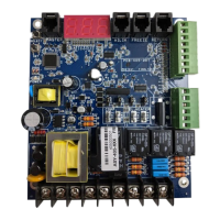
Provides physical dimensions of the PCB and standard cable lengths.
Lists and quantifies the required system inputs for the DDC module.
Details the physical terminal connections for AC power, system L2, and various outputs.
Specifies wire colors and connections for pressure transducers and sensors.
| Category | Diagnostic Equipment |
|---|---|
| Manufacturer | Dometic |
| Model | DDC |
| Display | LCD screen |
| Compatibility | Dometic refrigeration units |
| Power Supply | 12/24V DC |
| Software | Proprietary diagnostic software |
| Related Device | Dometic refrigeration units |