1
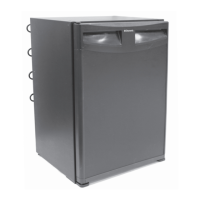
TILT SIDE-TO-SIDE
®
Refrigerator
Bulletin R74/6D
March 2002
PROCEDURE FOR
CHANGING COOLING UNIT
IN CARAVAN 95 AND NDR
REFRIGERATORS
The following categories have been established predicated on similarity of design and procedure for
replacement of cooling units:
A - CATEGORY #1
RM2193 RM2332 RM2333
RM2452 RM2453 RM2551
RM2552 RM2553 RM2554
RM4223 RM4290 RM4292
C - CATEGORY #3
RM1272 NDR1282
RM1282 NDR1292
NDR1272 NDR1492
B - CATEGORY #2
RM2620 RM2652 RM2820
RM2852 RM3662 RM3663
RM3862 RM3863 NDR1062
These instructions must be read and under-
stood before installation of this kit. This kit must
be installed by a Dometic service center or a
qualified service technician. Modification of this
product can be extremely hazardous and could
result in personal injury or property damage.
GENERAL INSTRUCTIONS TO ALL MODELS
1. Disconnect shore power from coach, the positive lead
from battery, and turn propane OFF at the tank.
2. Through lower vent, unplug refrigerator 120V AC cord(s)
from wall receptacle. Disconnect 12V DC wires from
terminal block on the refrigerator (if models have 12V
DC). Tape or cap ends.
3. Check again to make sure propane is OFF at tank, then
remove coach gas line from gas cock on refrigerator and
cap coach gas line.
4. For Models with Ice Maker: Turn water OFF to
appliance. Disconnect coach’s water line from water
solenoid (cap end).
5. Remove the refrigerator from alcove.
A. Category #1:
RM2193 RM2332 RM2333 RM4223
RM2452 RM2453 RM2551 RM4290
RM2552 RM2553 RM2554 RM4292
STEP 1. REMOVAL OF COOLING UNIT
1. See General Instructions on all models.
2. Loosen screws holding the thermostat bulb to fins. See
FIG. A1.
Note: Some models have a plastic thermistor bracket
clipped to the fin.
3. Remove the screws from the back wall of the freezer and
the fins.
Note: On models RM2452, RM2453, RM2551, RM2552,
RM2553 and RM2554, the fins are installed on the cooling
unit before it is put in the cabinet. The cooling unit must be
out of the cabinet before the fins can be removed.
4. On all other models remove the fins. See FIG. A1.
5. Lay the refrigerator face down on two 2x4’s to avoid
damaging the refrigerator front.
6. Remove cover from boiler and heating element(s).
7. Remove burner cover and then the burner assembly.
Note: Some models have a bracket that holds the manual
gas cock and/or the electric solenoid valve. Remove the
screws from these brackets and save to be reinstalled.
8. Cut the wire ties along the left side. Remove the
thermostat sensor tube (if required) and position the
burner assembly and wires so they will not be damaged
by pulling the cooling unit.
Important: After the cooling unit has been installed,
the initial start-up time can be shortened by tilting the
refrigerator from side-to-side and then from front-to-
back before the refrigerator is turned on. Hold in each
tilt position for approximately 30 seconds to settle
solution to bottom of cooling unit.
TILT FRONT-TO-BACK
Run the refrigerator on a bench for 12 hours after the cooling
unit has been installed. The refrigerator should not have food
in it during this test.
REVISION
Form No. 3107154.035 3/02
(Replaces 3107154.027)
©2002 Dometic Corporation
LaGrange, IN 46761