Circuit Diagrams of Electrical Appliances
21-114
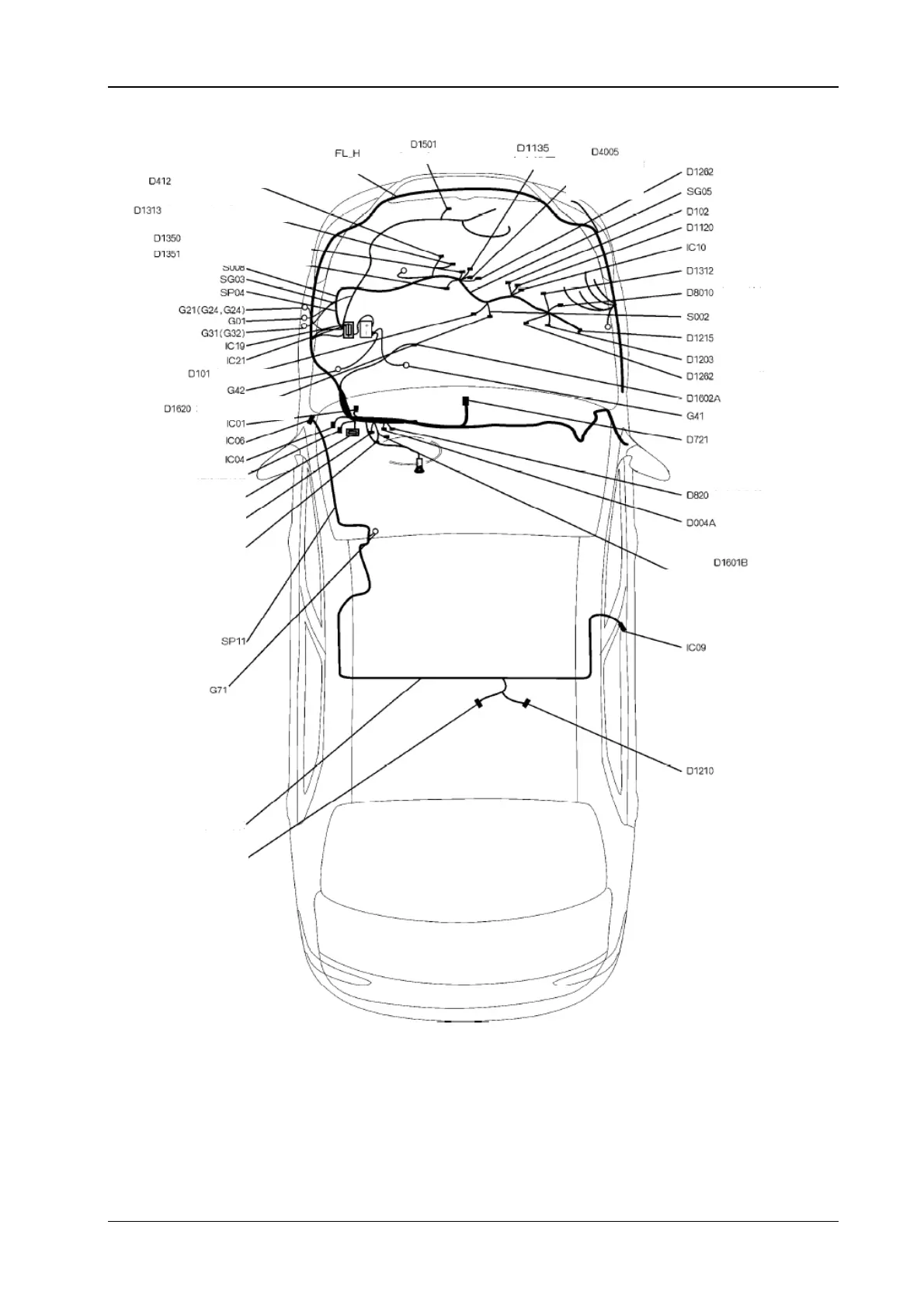
3.1 The electrical location diagram for the engine control S30/H30
En
ine oil senso
En
in
il
n
Coolin
fan moto
I
nition coil Engine water
temperature
sensor
Engine rotation sensor
ir dampe
Electric generator
The front oxygen sensor
The back oxygen sensor
The explosion and
Intake air pressure
ir conditioning
The carbon tank valve
The inertia switch
The accelerator pedal
The transmission unit
Th
t
rt
The vehicle speed
n
Multiple functional display
D1256 The oil
um
controlle
D001 The cabin fuse box
D003 The Dia
nostic a
aratus
D1694A The automatic transmissi
on control module
The ft protection controller
The combined instrument,
the blue
BD.H The cabin wirin
harness
D1211 The oil mete
The automatic transmission control
module
The fuel pump
 Loading...