Circuit Diagrams of Electrical Appliances
21-121
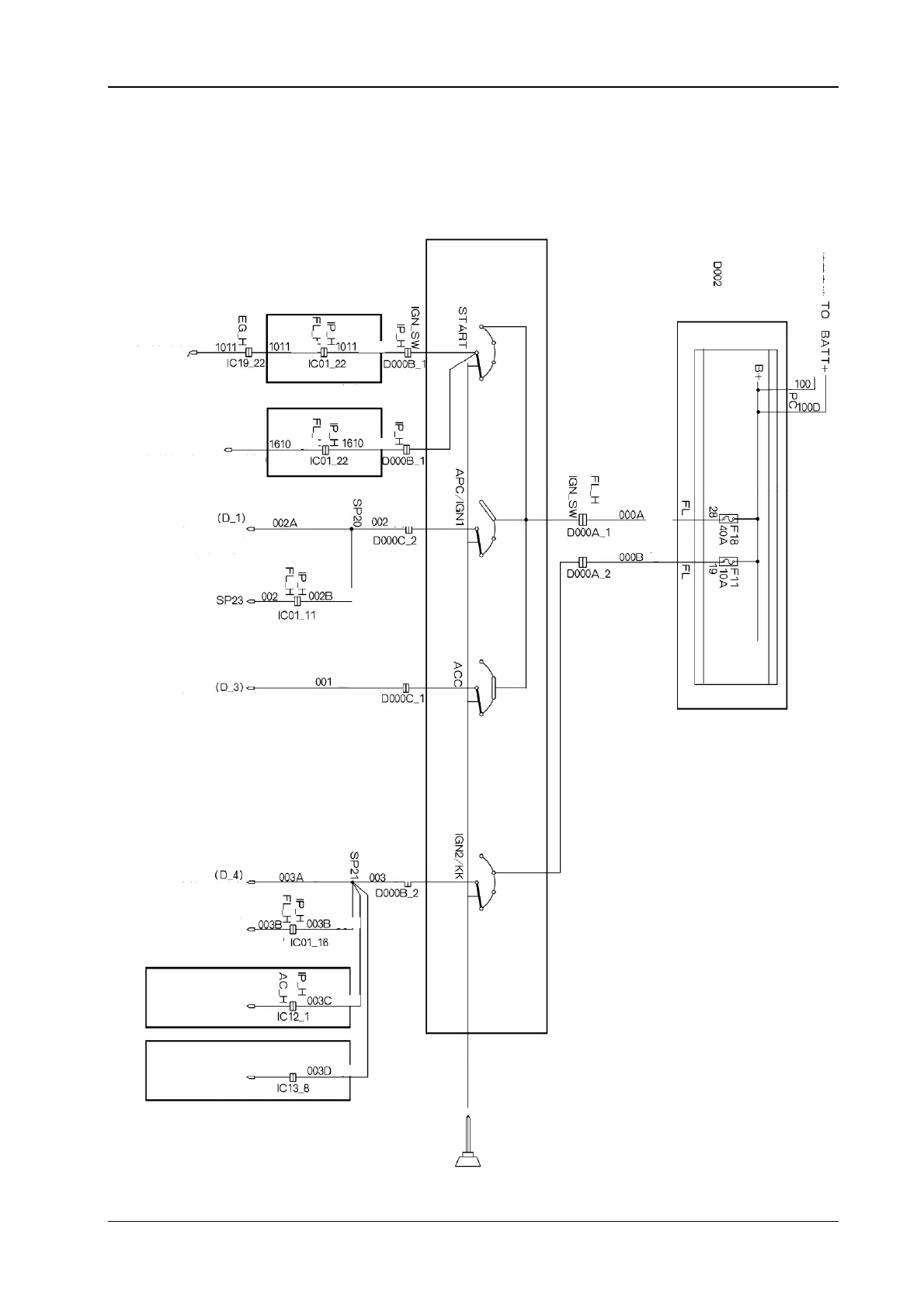
5.2 The electrical location diagram for the ignition switch S30/H30
D000Ignition switch
The starter moto
Green Green
Green Green
Red
Red
Red
Yellow
Blue
Green
Green
Green
White
Yellow
Brown
***It is used for manual
operated transmission
***It is used for automatic
transmission
The gear selection switch
(Refer to automatic gear and charging system)
The cabin fuse box
(the operation gear power source)
The engine compartment fuse box
(The operation gear power source)
The cabin fuse box
(The accessory shift power source)
The cabin fuse box
(The ignition gear power source)
The engine compartment fuse
(The fan relay, air conditioning pressure
switch)
*** It is used for manual air conditioning
*** It is used for automatic air conditioning
Manual operated air
conditioning control module
Automatic air conditioning
control module
The engine compartment fuse
To connect with battery
 Loading...