connect the DFPV Diag. main parts to the
vehicle diagnostic socket.
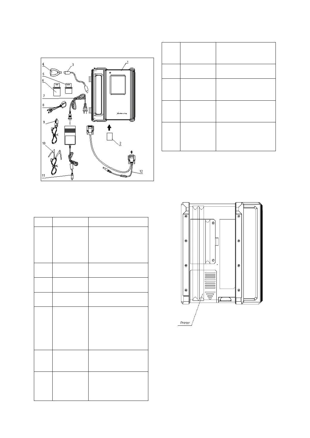
Figure 1-03
DFPV Diag. configuration is as shown in Figure
1-03.
No. Name Description
1
DFPV Diag.
Main Unit
unit can display the
operation buttons, the
help information.
2
Store diagnostic
software and data
3
Connect CF card
reader and computer
4
Read or write data
from/to the CF card
5
Diagnostic
connector
Dozens of connectors
are provided/available
for various vehicles.
Here shows a typical
6
diagnostic
7
100-240V (50-60Hz)
outlet and the power
8
connector
diagnostic socket
9
Get power from the
vehicle cigarette lighter
10
Battery
cable w/two
clips
vehicle battery
11
Power
adapter
power into 12V DC
power.
12 Main cable
diagnostic connector
and DFPV Diag. main
Printer Operation
Figure 1-04 shows the back view of the DFPV
Diag..
Figure 1-04
Mounting Paper
Miniprinter uses thermal paper with size of Φ
30 × 57mm (internal hole Φ 7mm). Refer to
Figure 1-05 for mounting the paper.
1. Open the housing of main unit and get out
 Loading...