Do you have a question about the Donner DED-500P and is the answer not in the manual?
This document is an installation instruction manual for the Donner DED-500 and DED-500P electronic drum kits. It provides a step-by-step guide for assembling the drum stand, attaching the pads and cymbals, installing the hi-hat stand, connecting the sound module, attaching the kick pedal, and wiring the components. The manual also includes information on performance preparation, such as adjusting the beater and understanding pad and cymbal sensing.
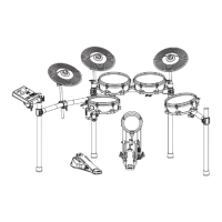
The Donner DED-500 and DED-500P are electronic drum kits designed for drumming practice and performance. They consist of a drum stand, various drum pads (snare, tom 1, tom 2, tom 3), cymbals (hi-hat, crash, ride), a kick pedal, a hi-hat pedal, and a sound module. The electronic nature of these kits allows for versatile sound options, adjustable volume, and the ability to practice silently with headphones. The sound module acts as the brain of the kit, processing the input from the pads and cymbals and generating the corresponding drum sounds.
The assembly process is broken down into several key stages:
Assemble the Stand: This involves connecting various straight and bent pipes to form the main frame of the drum kit. The pipes are labeled with lengths (e.g., 630mm, 820mm, 700mm, 350mm, 200mm) to guide the user. The initial steps involve creating the main curved structure, followed by adding the vertical support pipes. The final step in stand assembly is installing the pad mount holders, which will later secure the drum pads. The stand is designed to be expandable, with a recommended width of up to 1.4 meters.
Assemble the Pad: This stage focuses on attaching the drum pads (snare, tom 1, tom 2, tom 3) to the pad mount holders on the stand. Each pad is secured by inserting its mount into the holder and tightening a wing nut. The manual illustrates the placement of the snare and tom pads on the stand.
Attach the Cymbals (A-Attach the Cymbals): This section details how to mount the crash, ride, and hi-hat cymbals. The cymbals are placed onto a post, followed by a felt washer, a check bracket, and finally secured with a knob nut. A tightening screw is also used to further secure the assembly. It's important to align the cymbal with an indentation on the post before tightening the knob nut. The manual also highlights the "sensing range of cymbal," indicating the active area for triggering sounds.
Install the Hi-Hat Stand (B-Install the Hi-Hat Stand): This step is specific to the hi-hat assembly, which includes both a top and bottom cymbal, and a foot pedal. The diagram shows the hi-hat stand integrated into the overall drum kit structure. Crucially, the manual emphasizes that "the screw should be the same side of the hole" for proper installation of the hi-hat cymbals onto their rod.
Attach the Sound Module: The sound module is the central control unit. It is attached to the drum stand by inserting it and then adjusting a wing knob to fix it securely. An audio cable is connected to the sound module to complete this step.
Attach the Kick Pedal: The kick pedal assembly involves several parts: the pedal itself, a beater, and a stand. The kick drum stand needs to be fully opened and locked with screws on the sides. The beater is then installed into its holder and secured with a screw. Finally, the entire kick pedal assembly is securely installed. The manual provides guidance on proper beater positioning, suggesting it should be at the "center of kick drum" for optimal performance, whether playing "on the blanket" or "on the floot."
Power Connection and Wiring: This crucial step involves connecting all the drum pads, cymbals, and pedals to the sound module using the provided audio cables. The manual provides a clear diagram showing which component connects to which input on the sound module (e.g., Hi-Hat, Sound Module, Crash, Ride, Tom 1, Tom 2, Snare, Kick, Hi-Hat Pedal, Tom 3). An AC adapter is also connected to power the sound module. The instruction is to "Connect the jacks as shown in the figure."
The manual offers insights into how to interact with the drum kit for performance:
While explicit technical specifications like material or exact dimensions are not listed, the diagrams provide some implied information:
The manual does not explicitly detail maintenance procedures, but the assembly instructions imply certain aspects:
The manual concludes by showing two different models, DED-500 and DED-500P, indicating that the installation guide applies to both, but users should follow the specific instructions for the model they purchased. The visual difference between the DED-500 and DED-500P appears to be in the hi-hat stand design, with the DED-500P featuring a more traditional, floor-standing hi-hat pedal and stand, while the DED-500 integrates the hi-hat pedal directly into the main drum rack structure.
The back page provides comprehensive contact information for Donner, including email (service@donnermusic.com), website (www.donnermusic.com), and phone numbers for customer service in the United States, United Kingdom, Canada, and Australia. It also lists the manufacturer (GUANGZHOU RANTION TECHNOLOGY CO., LTD.) and its address, along with UK and EU representatives. This information is crucial for customer support and warranty claims.
Overall, this manual serves as a comprehensive guide for setting up and preparing the Donner DED-500/DED-500P electronic drum kits, focusing on practical assembly and initial adjustments for optimal performance.
| Model | DED-500P |
|---|---|
| Type | Electronic Drum Set |
| Connectivity | Headphone Output, AUX Input |
| Power Supply | DC 9V/1000mA |
| Included Accessories | Drum Sticks |