13
ENGLISHENGLISH
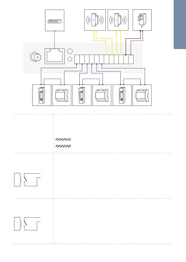
REL1 REL2 REL3 EXT1 EXT2 15VDC
max. 24 V, 1 A max. 24 V, 1 A
15 V DC, 1A
max. 24 V, 1 A
max. 0 V, 0 A
LAN/POE RJ45 jack to connect a standard Network cable Cat.5
or better, coming from the Internet Router/PoE-Switch/
PoE-Injector.
NOTICE
Do not power the device simultaneously via
the power supply from the power supply unit
(mains adaptor) and the power supply via PoE.
REL1, REL1
REL1
REL1
Bi-stable latching relay #1 (potential-free),
max. 24 V DC/AC, 1 A. Security feature: The relay keeps
its state even in the case of loss of power. You can
configure the default state of the relay (open/close) via
the DoorBird App. These ports can be used to connect
e.g. an electric door opener. The device does not supply
power to the connected device. The power supply for the
electric door opener must be installed separately.
REL2, REL2
REL2
REL2
Bi-stable latching relay #2 (potential-free),
max. 24 V DC/AC, 1 A. Security feature: The relay keeps
its state even in the case of loss of power. You can
configure the default state of the relay (open/close) via
the DoorBird App. These ports can be used to connect
e.g. an electric door opener. The device does not supply
power to the connected device. The power supply for the
electric door opener must be installed separately.
 Loading...