9
ENGLISHENGLISH
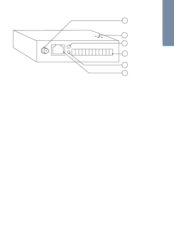
1) WiFi Antenna thread
Antenna thread to connect the
2.4 GHz WiFi Antenna supplied
with the device.
2) Loudspeaker
Loudspeaker for Diagnostic-
Sounds.
3) Diagnostic-LED
Diagonstic LED to visualize the
current status of the device.
4) Screw connection terminal
Screw connection terminal to
connect external devices such as
electric door openers and power
to the device.
5) Setup button
Setup button (SET) of the device,
to e.g. configure the WiFi interface
of the device using the DoorBird
App.
6) LAN/PoE jack
RJ45 jack to connect a
standard Network cable Cat.5
or better, coming from the
Internet Router/PoE-Switch/
PoE-Injector.
Device
WiFi Antenna
thread
Loudspeaker
Diagnostic-LED
Screw connection
terminal
Setup button
LAN/PoE jack
1
2
3
4
5
6
VIDEOS
Need help with the installation? Be sure to watch our installation videos
which can be found on http://www.doorbird.com/support
Each individual step of the installation is clearly documented in the videos.
 Loading...