ELECTRICAL INTERFACES
7
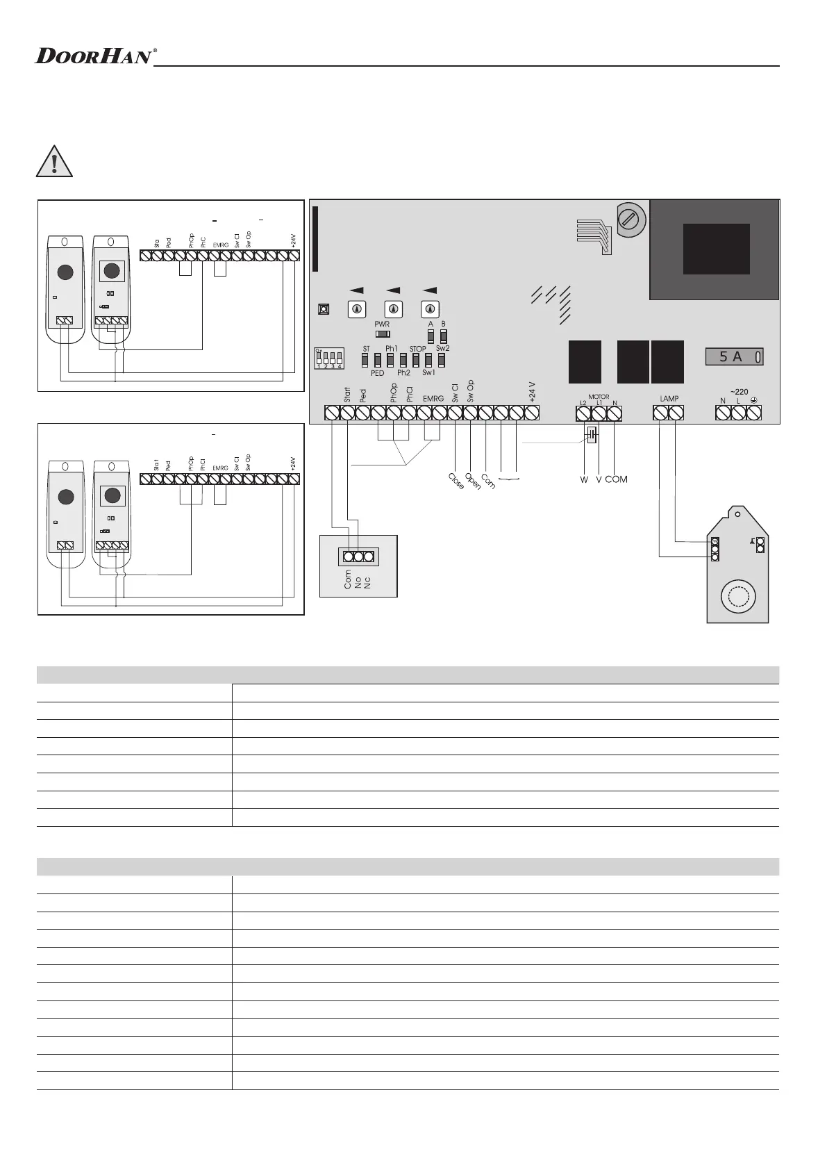
1.1. Wiring diagram of control unit
WARNING! Switch off the power before operating with control board. Always install power cables apart from signal
ones. Use a braided shield cable to reduce induces noise. The wires in the cable shall be protected from contact with
any rough and sharp details.
1. ELECTRICAL INTERFACES
1.2. Description of elements of control unit
Elements of control unit
Contacts of control unit
E l e m e n t s Description
TR1 Transformer
J0 Quick connector for receiver
DIP Group of DIP-switches
FUSE High-voltage fuse
FUSE2 Low-voltage fuse
TIMER W Adjustment of reverse time after limit switch response
AUTO CL Time delay before automatic closing
FORCE Adjustment of traction force
P i n s Description
~220 (N, L, PE) Supply voltage
Motor (N, L1, L2) Pin to connect motor
Lamp Pin to connect warning light (see diagram)
– Negative terminal for accessories power supply (24 V), 600 mA
+24 V Positive terminal for accessories power supply (24 V), 600 mA
Sw Op Output contact of limit switch to open
Sw Cl Output contact of limit switch to close
EMRG Contact pair for emergency stop (NC)
Ph Op Output contact for photocells to open (NC)
Ph Cl Output contact for photocells to close (NC)
Ped Command to close (DIP2 is on) (NO)
Start Command to open or step-by-step control (NO)
N
com
DCP(+)
com
com
com
r
GND
com
DC.P
com
com
com
LED3
GND
VCC
(+24)
CON2
LED2
GND
VCC
(+24)
CON1
LED1
IR
COM
NO NC
com
DC.P
com
com
com
LED3
GND
VCC
(+24)
CON2
LED2
GND
VCC
(+24)
CON1
LED1
IR
COM
NO NC
Timer W Auto CL Force
Fuse 2
FuseDIP
J1J2J3J4
J0
Connecting photocells to close. Set the jumper to NC when using photocells PhotoCell
(DoorHan)
Connecting photocells to open. Set the jumper to NC when using photocells PhotoCell
(DoorHan)
Receiver
Jumpers
Capacitor
Red
Black
Green
Blue
Red
Limit switches
LED
Observe the polarity
External control button
3