This document provides programming instructions for the DoorHan PCB-SW control board, detailing electrical connections, operator programming, and transmitter programming.
Device Function Description
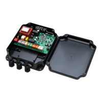
The DoorHan PCB-SW control board is designed for managing gate operators, offering a range of functionalities for both basic and advanced control. It supports various operational modes, including manual and automatic learning, and allows for the integration of safety devices, auxiliary lighting, and traffic lights. The board features two eight-segment indicators for displaying the status of control board switching contacts and gate movements.
Important Technical Specifications
Electrical Connections
- Control Board Power Supply: 220 V AC.
- Motor Power Supply: Connects to 220 V AC for gate leaves No. 1 and No. 2.
- Signal Lamp: Connects to 220 V AC.
- Photocells Power Supply: 24 V.
- Additional Accessories Power Supply: 24 V (max 500 mA).
- Electromagnetic Lock Connection: Requires an intermediate relay with a power supply voltage of 24 VDC and a switching current of 10 A.
- Electromechanical Lock Connection:
- Up to 3A: Direct connection.
- Over 3A: Requires an intermediate relay with a power supply voltage of 24 VDC and a switching current of 10 A.
- Auxiliary Lighting Connection: Requires an intermediate relay with a power supply voltage of 24 VDC and a switching current of 10 A.
- Traffic Lights Connection: Requires an intermediate relay with a power supply voltage of 24 VDC and a switching current of 10 A.
- End Position Reader: Supports close and open direction end switches for gate leaves No. 1 and No. 2.
- External Antenna: Connects to the external antenna of the remote control receiver.
Programming Parameters (Default Values)
- Operation Mode (P0):
n (operation on limit switches).
- Delay of 1st Leaf Closing (P1):
2 (5 seconds).
- Delay of 2nd Leaf Opening (P2):
2 (2 seconds).
- Control Board Setting (P3):
Ln (force, deceleration, and operation time).
- Automatic Gate Closing (P4):
0 (off).
- Auxiliary Lighting (P5):
0 (flashing during closing, solid during opening).
- Cycles Counter (P6):
00 (one division corresponds to 1000 cycles).
- Pass Door or Single-Leaf Gate Automation Mode (0.0):
n (disabled).
- Force on 1st Leaf (0.1):
3 (medium force).
- Force on 2nd Leaf (0.2):
3 (medium force).
- Maximum Force at the Start (0.3):
n (disabled).
- Pre-activation of Signal Lamp (0.4):
n (disabled).
- Operation Logics of Electric Lock Terminals (0.5):
n (electromechanical).
- Closing Safety Devices Activation (0.6):
n (immediate reverse movement).
- Automatic Gate Closing After Activation of Photocells (0.7):
n (disabled).
- Gate Opening/Closing with Buttons Held Pressed (0.8):
n (disabled).
- Prohibition of Control Commands Acceptance During Gate Opening (0.9):
n (disabled).
- Separate Control Logics (1.0):
n (disabled).
- 1st Leaf Opening Time with PED Button (1.1):
0 (disabled).
- Remote Programming (1.2):
Y (enabled).
- Reset to Factory Settings (9.8):
rE.
Usage Features
Electrical Connections
- Safety Precaution: All connections must be made with the power turned off. Cable wires should be protected from contact with rough or sharp details.
- Lock Connections: Electromagnetic and electromechanical locks may require an intermediate relay depending on their power requirements.
- Auxiliary Devices: The board supports connections for signal lamps, photocells, auxiliary lighting, and traffic lights, enhancing the functionality and safety of the gate system.
- Antenna: An external antenna can be connected to improve the range of the remote control receiver.
Operator Programming
- Basic Programming:
- Accessed by pressing the "P" button.
- Allows selection and adjustment of parameters like operation mode, closing/opening delays, control board settings, automatic closing, auxiliary lighting behavior, and cycle counter.
- Changes are saved by pressing "P" and exiting with "R".
- To exit without saving, press "R".
- Manual Learning:
- Requires closing the gate and locking the drives.
- Involves pressing "P" to initiate movement and "+" to confirm end positions for both leaves during opening and closing cycles.
- Two short beeps indicate successful programming.
- Deceleration can be set by pressing "+" during leaf movement.
- Automatic Learning:
- Similar to manual learning, but deceleration can be adjusted by pressing "+" during leaf movement.
- If safety devices are triggered, an "Er" (Error) message will flash, requiring the error to be resolved and learning repeated.
- Advanced Programming:
- Accessed by pressing and holding the "P" button for 10 seconds.
- Allows adjustment of more detailed parameters such as force settings, pre-activation of signal lamps, electric lock logic, safety device activation, and remote programming.
- Changes are saved by pressing "P" and exiting with "R".
- To exit without saving, press "R".
- Display Indication: The two eight-segment indicators show the status of various contacts (FOTO OP, FOTO CL, PED, SBS, STOP) and processor operation.
- Energy Saving Mode: The display automatically turns off after 3 minutes of inactivity. Pressing any button resumes display operation. In this mode, photocell power supply (terminal X7) is turned off.
Transmitter Programming
- Receiver Memory Clearing: Press and hold the "R" button for 20 seconds after power-on until a long audio signal is heard.
- Recording Transmitters:
- Press and hold "R" until "00" appears on the display.
- Press the desired button on the transmitter twice.
- A short click confirms successful programming.
- The display shows the number of recorded transmitters.
- Up to 100 transmitters can be recorded.
- Multichannel transmitters can be recorded to control opening and closing separately.
- The unit automatically exits recording mode after 20 seconds of inactivity.
- Programmed data is retained even if the control unit is disconnected from power.
- Three long audio signals indicate receiver memory overflow.
- Remote Programming of DoorHan Transmitters:
- Requires a programmed transmitter.
- Press and hold button 2, then press and hold button 1 on the programmed transmitter (within 5 seconds).
- Release both buttons.
- Press the programmed transmitter button to enter programming mode.
- Press the desired button on the new transmitter twice.
- A short click confirms successful programming, and the display shows the number of recorded transmitters.
- Programming should be done within the operating range of the receiver.
- Dots on the transmitter body indicate button numbers.
- Multichannel remotes (T5PRO/T15PRO) use two memory cells.
Maintenance Features
- Reset to Factory Settings:
- Enter advanced programming, select item "9.8".
- Press "P", "rE" will appear.
- Press and hold "P" for five seconds until "rE" stops flashing and a short audio signal is heard.
- This operation reloads the board with default settings but does not erase receiver memory.
- Software Version: The software version can be checked in the advanced programming menu (item 9.9).