Loop Info-Q-2-16
9
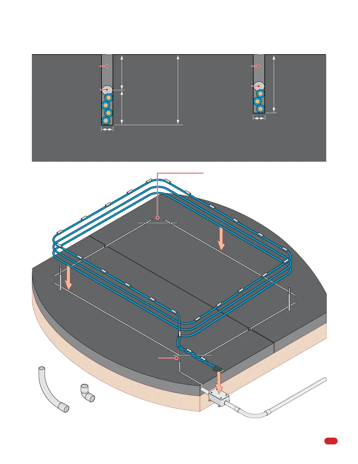
Continuous length of wire (NO Splices).
Cutaway of Underground Loops
1” Foam backer rod
spaced every 1 ft in saw cut
holds wires in place.
Sealant
1/2” to 3/4” Min.
Roadway
Sealant even with road surface. Sealant even with road surface.
4 Turn Loop or Greater 3 Turn Loop or Less
1” depth
1 1/2”
Typical
2”
Typical
3/16” to 1/4” Saw Cut
3/16” to 1/4” Saw Cut
Roadway
45° corner
saw cut.
45° corner
saw cut.
Straight saw cut.
Drill approx. 1/2” hole in expansion joint (If existing)
to give loop
w
ires
room to move during roadway
exp
ansion and contraction
.
Straight saw cut.
45° corner
saw cut.
Twist wire from this
point to loop detector.
Exit Slot
NO Sharp
Angles
Watertight J-Box
Sweep
Loop Lead-In Wire or Cable
to Operator in
PVC Conduit
Tape on end to hold
wires together.
Straight saw cut.
Straight saw cut.
DO NOT allow the straight saw cuts to connect in
the corners or the triangular roadway pieces that are
created will eventually break free from the roadway.
Depth will vary
depending on the
number of wire
turns.
Backer Rod
Sealant
Note: Use only sweeps for 90° conduit bends. Do not
use 90° elbows as this will make wire pulls very
difficult and can cause damage to wire insulation.
NO 90° Elbows
Sweep
Drawings not to scale
Expansion Joint (If existing)
1” foam backer rod
spaced every 1 ft. in saw cut.
 Loading...