Loop Info-Q-2-16
2
INTRODUCTION
A loop detection system is a method of sensing vehicles and is typically used in automated gate applications to prevent a
gate from automatically closing on a vehicle or to automatically open the gate when a vehicle is exiting a property. Vehicle
loops can also be used to activate card readers, ticket spitters, etc. When properly installed, loops are an extremely
reliable form of vehicle detection. The loop detection system operates by creating an electrical field of sensitivity that
tunes to the surrounding environment. When a metallic object enters this electrical field, the loop detector senses a
change in the field and generates an output, usually activating a relay in a gate operator or other access control device that
controls the operation of the gate.
There are three basic components in a loop detection system:
• Underground loop
• Loop lead-in wire or cable
• Loop detector
Proper installation of the loops is essential for reliable functioning of the detector system. Most detector problems are caused
by improper loop installation! The geometry (size and shape) of the loop defines the detection zone characteristics.
• Loop size may vary and will depend on lane width, traffic patterns, and types of vehicles to be detected.
• The short leg of any loop used for vehicle detection should never be less than 18 in. The height of detection is directly
related to the length of the short leg of the loop. A general rule of thumb to follow is that the height of detection is
1/2 to 2/3 the length of the short leg of the loop.
• Normal loops (4 ft x 8 ft) are used to detect motorcycles and automobiles. Minimum size for loops to detect typical
vehicular traffic is 18 in x 48 in. It is always recommended to use a larger loop whenever possible.
• Maximum “detection height” of a loop is 3 to 4', which may be achieved with a loop measuring 6' on the short leg.
• Loops can be saw cut into concrete or asphalt. They can be placed under brick pavers and asphalt or be imbedded in a
poured concrete road surface.
Design Facts
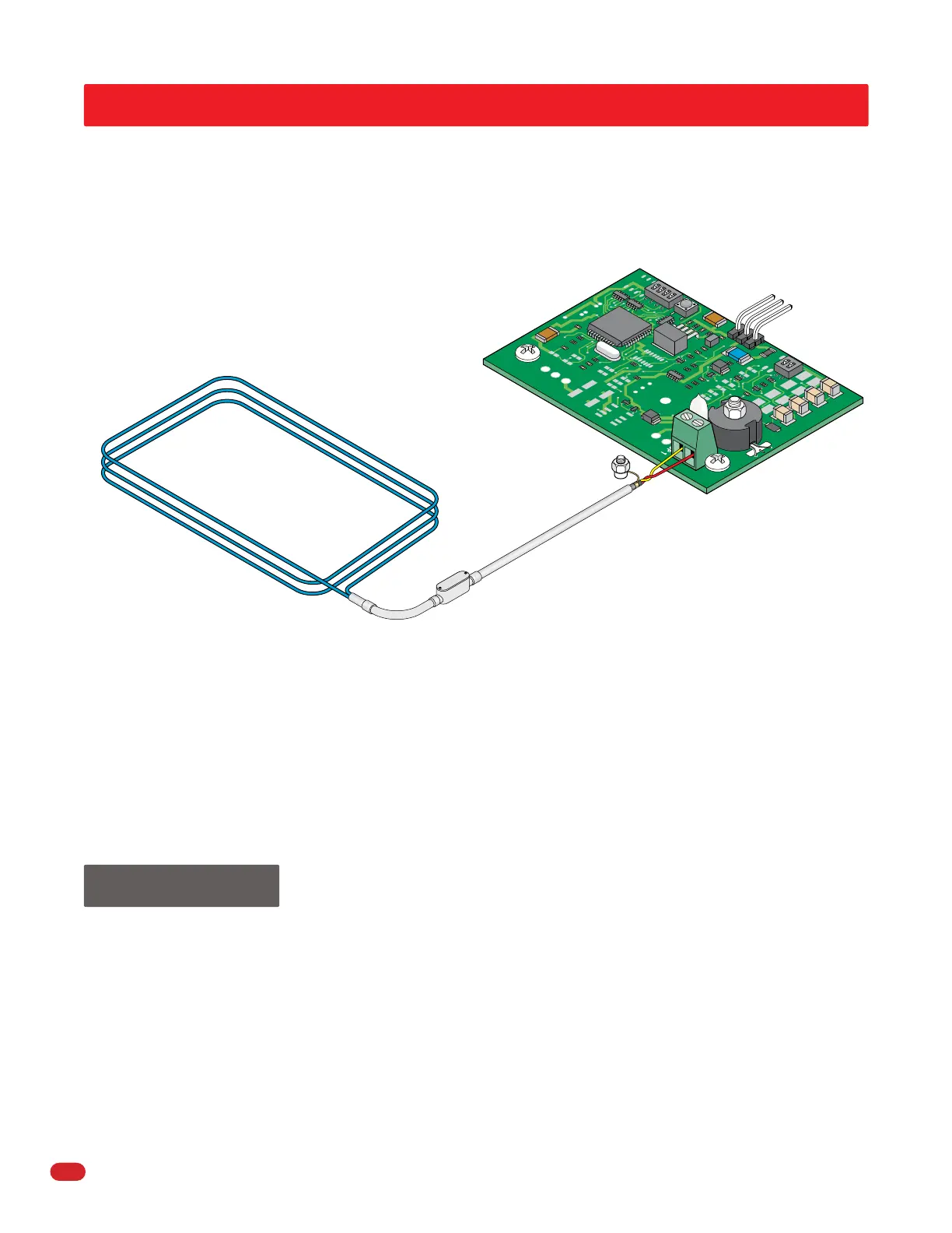
Underground Loop
The loop is made from a continuous
piece of wire (NO SPLICES) that is
coiled around for a number of turns
in a square or rectangular pattern.
The wire is embedded into pavement
either as a preformed loop placed
prior to paving, or into a saw cut that
is cut into existing pavement. Both
ends of this wire are then extended
to the edge of the pavement.
Loop Lead-In Wire or Cable
The lead-in wire or cable extends the two
ends of the loop wire back to the loop
detector. On short runs (Loop is within ten
feet from the loop detector), the two wires
exiting the loop can be twisted together,
run in conduit to the operator and
connected directly to the loop detector.
The lead-in wire: DoorKing recommends
that lead-in wire be twisted a minimum of six turns per foot.
The lead-in cable: If additional lead-in wire is required, DoorKing recommends that you
use a shielded twisted pair (Insulated (floated) at one end and grounded at gate opera-
tor) with a direct burial rated jacket or be placed in PVC conduit. All splices must be
soldered and placed in a watertight J-box.
Loop Detector
The loop detector is the electronic
component that controls the loop
system. DoorKing offers loop detectors
(Models 9409, 9410 and 9411) that plug
directly into the gate operator control
board, eliminating the wire harness and
wiring connections other than the loop
lead-in wires. These detector boards have
a terminal strip where the loop lead-in
wire connects. There are also various
other types of standalone detectors
available on the market that can be hard
wired into the gate operator control
board.
Loop with
3 Wire Turns
Operator Chassis Ground
(See page 6 for
grounding restrictions).
Long Leg Length
Soldered Spliced Connections
in Watertight J-Box
PVC Conduit
Short Leg Length
 Loading...