10
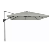
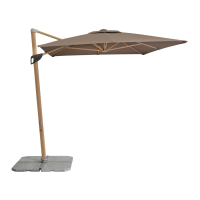
Mounting the balcony blind
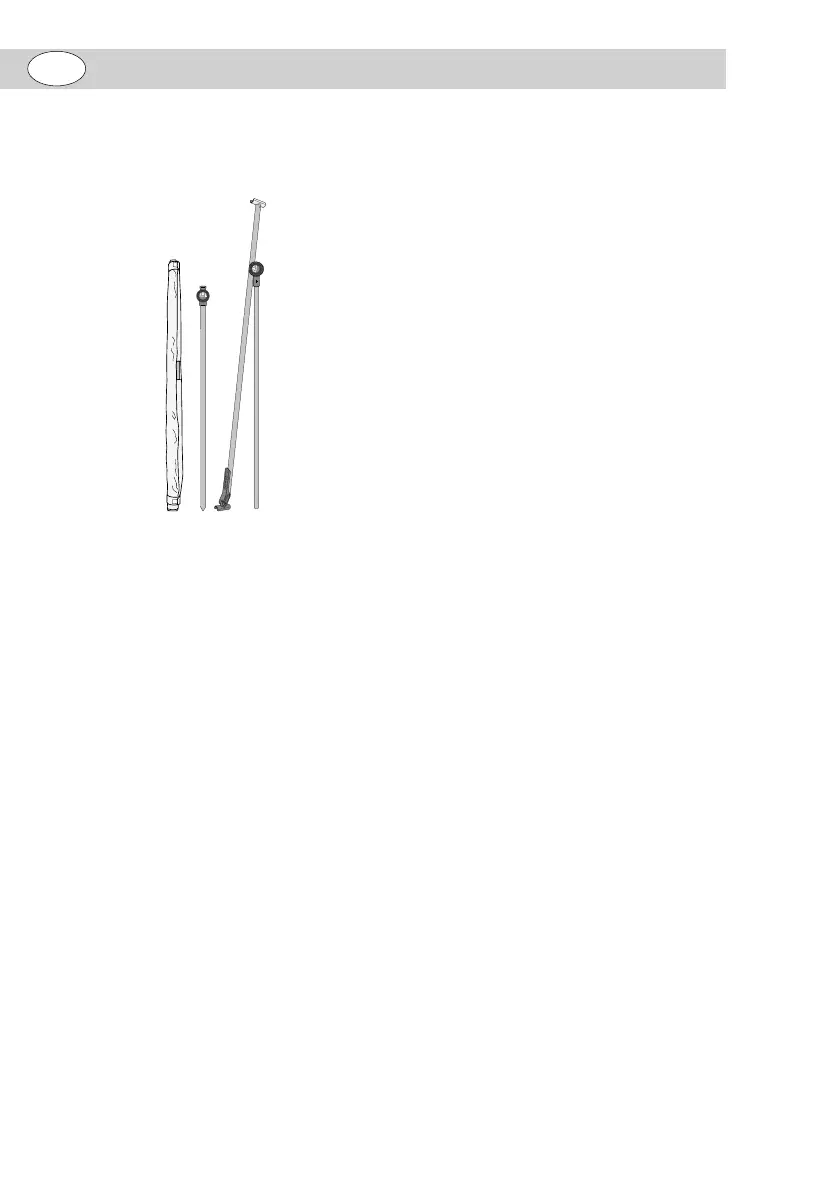
In the box, you will find:
– Balcony blind in 3 pieces
1 2 43
Please note:
– The balcony blind is delivered without
a stand system.
1. Put the bottom pole 2 in a base and
fix it in place there. See the assembly
instructions for the base for this (see
figure B).
2. Let the upper pole 4 with the lateral
brace 3 slide at least 10 centime-
tres into the bottom pole 2 and fix it
in place using the knob 5by turning it
clockwise (see figure C)
3. Release the two hook and loop strips 6
from the balcony blind 1 and roll the
balcony blind 1 out (see figure D).
4. Fix the hook and loop strips 6 on the
corresponding loop-sides 7 (see fig-
ure D).
5. Let one reinforcing brace 8 lock into
the holder 9 of the lateral brace 3 with
an audible CLICK! (see figure E).
6. Attach the other reinforcing brace 10
to the holder 11 of the lateral brace 3
and fold the locking mechanism le-
ver 12 towards the pole (see figure F
and G).
Adjusting the length of the
upper pole
(see figure C).
Please note!
– The upper pole 4 must be inserted into
the bottom pole 2 by at least 10 cen-
timetres. Otherwise, the upper pole 4
may not be in stable position.
1. Loosen the knob 5 by turning it anti-
clockwise.
2. Pull the upper pole 4 out of the bot-
tom pole 2 or push it inwards until you
reach the desired height.
3. Tighten the knob 5 by turning it clock-
wise.
Moving, tilting, or pivoting
the lateral brace
You can modify the position of the lateral
brace 3 relative to the upper pole 4, if, for
example, the base can only be placed in
a certain position on your balcony.
Please note!
– When opening and closing the
knob 13, always take hold of the lat-
eral brace 3 with one hand.
– When moving the lateral brace 3,
make sure that it doesn’t protrude
over the mark on each side (see fig-
ure H).
1. Open the knob 13 by turning it an-
ticlockwise until the gearing 14 is
opened as far as needed to be able
to freely rotate the joint (see figure I).
2. Move, tilt or pivot the lateral brace 3
to the desired position (see figure J
and K).
3. Tighten the knob 13 by turning it
clockwise.
GB