G
Gary WheelerSep 23, 2025
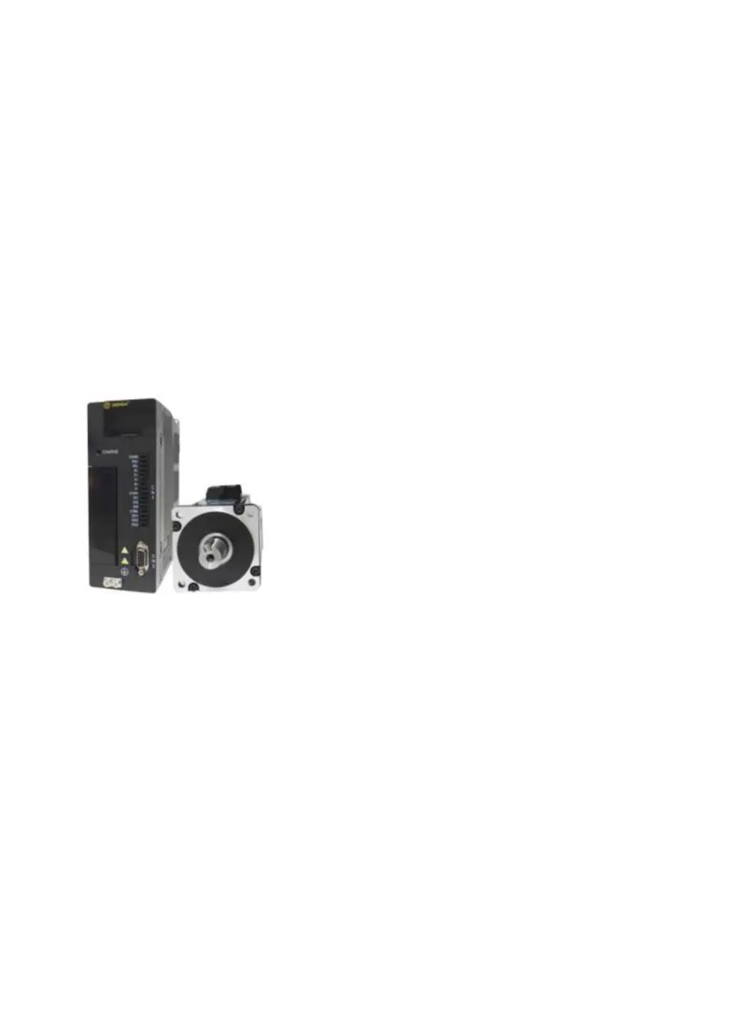
What to do if Dorna Industrial Equipment current detection channel 2 abnormal?
- EEmily JohnsonSep 23, 2025
If your Dorna Industrial Equipment has an abnormal current detection in channel 2 due to an internal circuit issue, power off the equipment and power it on again after 1 minute. If the alarm persists, contact the manufacturer.