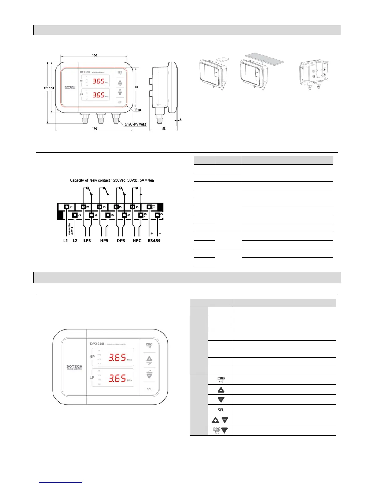
2. INSTALLATION
:DIMENSIONS AND MOUNTING(unit: mm)
※ Please install a siphon tube to protect from pulsating pressure and high temperature contact.
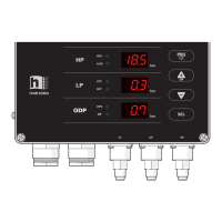
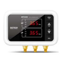
LP : Low Pressure | OP : Oil Pressure | HP : High Pressure
(unit : mm)
: WIRING DIAGRAM
No Connection Description
1 L1
100–240Vac, 50/60Hz Power Input
2 L2
3
LPS
Open when the low pressure is below lower limit
4
Common signal
5
HPS
Open when the high pressure is above the upper limit
6
Common signal
7
OPS
Open when the oil pressure is below lower limit
8
Common signal
9
HPC
Closed when the high pressure is above the upper limit
10
Common signal
11
RS485
TRX + signal
12
TRX – signal
3. USER INTERFACES
: DISPLAY AND CONTROLS
Description
DP
On when displaying differential pressure
LED
HPS
ON/OFF of Output / ON when Overpressure
HPC
ON/OFF of Output / ON when Fan is Running
ALM
On when alarm occurs
OP
On when displaying oil pressure
LPS
ON/OFF of Output / ON when Underpressure
OPS
On/Off of output / On when oil pressure
RST
ON when Manual Reset
Button
Parameter Settings / Manual Reset(if pressed twice quickly)
Increase or Move Up
Decrease or Move Down
Select & Save / Display of Saturated Temperature
Display differential pressure value, oil pressure value
 Loading...