Lit. No. 41936, Rev. 00 5 August 15, 2015
41000
SETUP
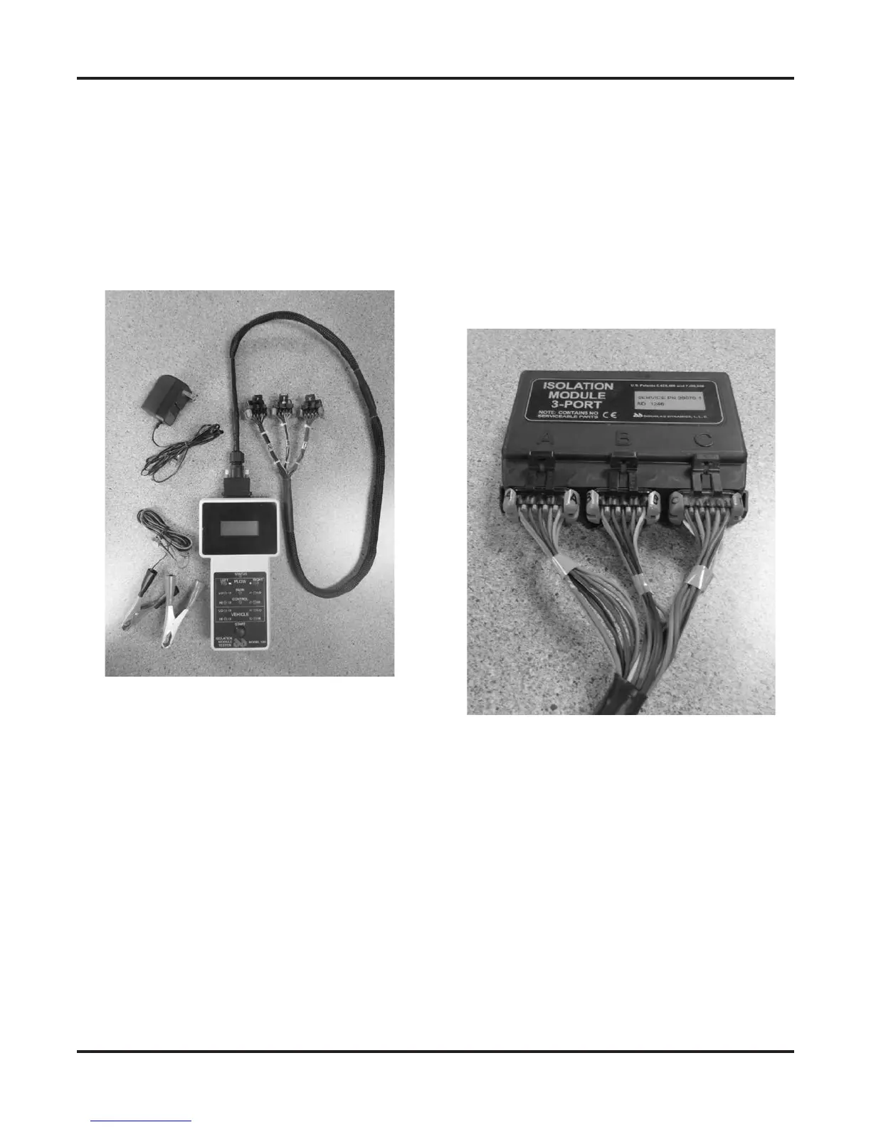
The Isolation Module tester comes with a transformer,
for plugging the tester into a 110V AC outlet, and a set
of red and black alligator clips, for powering the tester
from a 12V vehicle battery.
The supplied tester harness is used to connect the
tester to the isolation module.
1. Plug the transformer into a wall receptacle or
connect the alligator clips to the vehicle battery
terminals:
• Red clip to POS (+) battery terminal.
• Black clip to the NEG (–) battery terminal.
When disconnecting, remove the black alligator
clip rst, then the red alligator clip.
Do not plug the green 2-pin connector into the
tester yet.
2. Connect the harness 26-pin connector to the top
of the tester, turning the 2 knobs to secure the
connector.
3. If the isolation module to be tested is installed in a
vehicle, disconnect the harnesses from the A, B,
and C ports of the module.
4. Connect the 10-pin plugs of the tester harness,
labeled A, B, and C, to the corresponding ports on
the isolation module.


 To Next Page