D
David LindseyAug 7, 2025
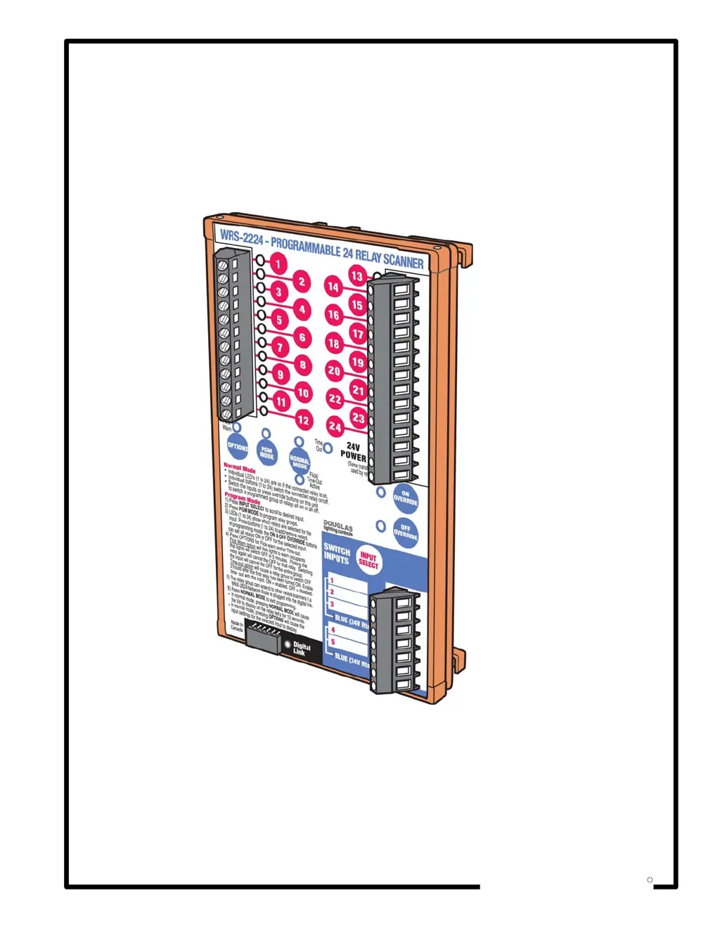
What to do if Douglas Lighting Controls WRS-2224 output relay(s) not tripping properly?
- JJohn SandovalAug 7, 2025
If the output relays on your Douglas Lighting Controls Scanner aren't tripping properly, several factors could be at play. First, ensure that the input voltage is within the required range of 22V to 30VAC by checking the input configuration, switching devices, connections, and power source. Also, if you're using non-default input switching devices, make sure the inputs are correctly configured. Another potential issue is the relay being part of another input group with conflicting input signals; if so, remove the relay from the other group. Finally, verify that the relay is included in the input group and re-program if necessary.