4
General Information
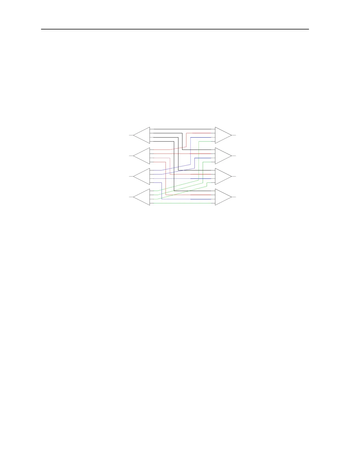
1.4 CB Matrices
CB-Series stands for Crossbar. It is a matrix with several inputs connecting to
several outputs. Only one input can be connected to one output at any given
time.
The switches are populated inside the matrix chassis and are interconnected so
that any input can connect to any output and vice versa. All input/output RF
ports are available to the user on the rear panel of the matrix. Depending on the
size of the switch and the quantities needed, the matrix size can grow from
2RU to 4RU (or even larger).
SW1
SW2
SW3
SW4
Output 1
Output 2
Output 3
Output 4
Input 1
Input 2
Input 3
Input 4
SW8
SW7
SW6
SW5
1
2
3
4
1
2
3
4
1
2
3
4
1
2
3
4
1
2
3
4
1
2
3
4
1
2
3
4
1
2
3
4
Example of a CB series matrix with 4 input and 4outputs.
Part Numbering Examples:
CB-4U18S-10X10-GPIB
A CrossBar matrix with following characteristics:
4U, 18 GHz, SMA, 10 inputs 10 outputs, GPIB
CB-4U18N-8X8- GPIB
A CrossBar matrix with following characteristics:
4U, 18 GHz, N connectors, 8 inputs 8 outputs, GPIB
CB-2U18S-4X4- GPIB
A CrossBar matrix with following characteristics:
2U, 18 GHz, SMA, 4 inputs 4 outputs, GPIB
CB-[chassis size][frequency][connector]-[number of inputs]X[number of outputs]-[remote control type]
[chassis size]: 1U | 2U | 3U | 4U etc.
[frequency]: 12 (for 12.4 GHz) | 18 (for 18 GHz) | 26 (for 26.5 GHz) | 40 (for 40 GHz)
[connector]: B (for BNC) | N (for N) | S (for SMA) | K (for 2.9 mm)
[number of inputs]: 2 | 3 | 4 | 5 … 10 | 12 | 16| 20 (or more if chassis size allows)
[number of outputs]: 2 | 3 | 4 | 5 … 10 | 12 | 16| 20 (or more if chassis size allows)
[remote control type]: ENET (for Ethernet, RS-232, USB) | GPIB (for IEEE-488, USB)
 Loading...