Do you have a question about the Dr.Fodisch MCA 10 HWIR and is the answer not in the manual?
Details on how to use the operation manual effectively.
Defines the purpose and scope of the MCA 10 HWIR analyser.
Outlines the manufacturer's warranty terms and conditions.
Lists applicable European and German standards.
States compliance with fundamental safety and health requirements.
Explains signal words (DANGER, WARNING, CAUTION, NOTICE) for hazards.
Details specific hazards like voltage, explosion, poisonous/corrosive substances, and heat.
Lists required PPE: clothing, footwear, gloves, head, respiratory, eye, hearing.
Defines qualifications and responsibilities for operating personnel.
Details safety precautions for electrical power supply and grounding.
Safety instructions related to hazardous gases and cylinder handling.
Notes on using original parts and avoiding damage to components.
Precautions for handling electronic components to prevent ESD damage.
Warns against unauthorized configuration changes that affect safety.
Explains the principle of gas component measurement using infrared light.
Describes the method using measuring and reference filters for gas detection.
Explains the method using a gas-filled reference filter for absorption measurement.
Details the functional principle of oxygen measurement using a zirconium dioxide cell.
Presents a table of cross-sensitivities and required compensation.
Lists industries and applications where the MCA 10 HWIR is used.
Describes the optical components of the analyser.
Explains the gas suction mechanism and pressure standardization.
Lists main components located at the top and bottom of the device.
Details the components of the emitter unit, including IR emitter and chopper wheel.
Describes the cuvette's optical path and mirrors for gas measurement.
Explains the detector unit, filter wheel, and over-temperature protection.
Details the gas distribution block and its connections.
Explains the role of pressure sensors in standardizing measurements.
Describes the placement of the optional oxygen sensor.
Outlines the mainboard's responsibility for control and communication.
Details the power supply unit and its voltage levels.
Lists the available communication interfaces (USB, RS232, RJ-45).
Shows physical connections for power, gas, and communication.
Illustrates a system setup with optional additional devices.
Provides a diagram of the gas flow and control system.
Explains the interaction between the analyser, PC, and cabinet control.
Details communication paths and tasks between system components.
Explains the layout and status indicators of the main operating screen.
Describes how to navigate and interact with menu elements.
Details how to input values using numerical buttons and function buttons.
Explains the screen display during data exchange between the analyser and PC.
Shows the hierarchical organization of the analyser's menus.
Defines different access levels based on password protection.
Describes the main menu layout, language selection, and device information.
Guides users on how to input passwords to access different levels.
Displays current measuring results for IR components and oxygen sensor.
Shows the time-based development of gas concentrations.
Allows switching the maintenance mode and selecting gas sources.
Provides access to general system information and measuring values.
Lists current and historical messages, categorised by type.
Triggers the automatic zero point setting process for IR components.
Allows setting calibration parameters for IR components, O2 sensor, and flow.
Enables modification of calculation-relevant and system-relevant parameters.
Provides unlimited access, reserved for authorized service personnel.
Lists components and their required maintenance intervals.
Step-by-step guide for replacing the injector screwing-in.
Procedures for replacing cuvette filters and gaskets.
Guide for replacing screwing-in with nozzle in the gas distribution block.
Defines service qualification levels for error handling.
How to view and clear error messages on the visualization PC.
Lists failure messages, their causes, and recommended actions.
Lists maintenance messages, their causes, and recommended actions.
Lists maintenance requirement messages, their causes, and recommended actions.
Lists informational messages and their causes/actions.
Procedures for safely shutting down the device and system.
Steps for safely disassembling the analyser and its components.
Specifies ambient conditions for correct device storage.
Guidelines for environmentally responsible disposal of the device.
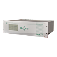
Lists technical specifications for the analyser unit.
Details technical specifications for the photometer module.
Provides measurement ranges for various gas components.
Lists components and item numbers for ordering (1/3).
Lists components and item numbers for ordering (2/3).
Lists components and item numbers for ordering (3/3).
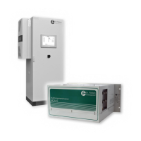
Describes the features and layout of the analyser cabinet.
Safety precautions and methods for transporting the analyser cabinet.
Guidelines for correctly placing the analyser cabinet.
Guidelines for correctly mounting the analyser cabinet.
Steps for initial setup and commissioning of the analyser cabinet system.
Explains the automatic zero point adjustment based on temperature.
Procedures for providing test gas for calibration and verification.
Details on performing local test gas provision.
Instructions for test gas provision using an optional gas sample probe.
Maintenance tasks and intervals for the system and its components.
Refers to the MCA 10 HWIR's error handling procedures for the system.
Procedures for shutting down and disposing of the analyser cabinet system.
Steps for safely disassembling the analyser cabinet.
Specifies ambient conditions for analyser cabinet storage.
Guidelines for responsible disposal of the analyser cabinet.
Lists technical specifications for the system and analyser cabinet.
Lists spare and wear parts for the system and analyser cabinet.
| Brand | Dr.Fodisch |
|---|---|
| Model | MCA 10 HWIR |
| Category | Measuring Instruments |
| Language | English |