CONTACT US AT www.DRpower.com 9
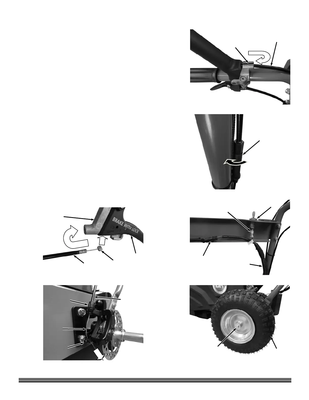
9. Pull the Traction Drive Cable Sheathing to the front to expose the Braided
Cable and insert the Braided Cable into the Bracket slot (Figure 9). Push the
Sheathing into the hole at the front of the Traction Drive Handle Bracket.
10. Turn the Traction Drive Cable Adjuster clockwise (looking from top) to
extend the adjuster to tighten the Cable (Figure 10). Only tighten enough so
the Lever rests lightly against the Bracket with no gap (play) between.
11. Connect the Operator Presence Connector and two Key Switch Terminals
behind the Cross Member (Figure 11).
12. Loosen the Bolt of the left side Wheel using a 1/2" Wrench (Figure 12).
13. Support the machine with wood blocks to raise the left side Wheel slightly
off the ground.
14. Remove the Bolt, Lock Washer, large Flat Washer and left side Wheel
Assembly from the Axle. Take note of the Key that is in the Axle Keyway, if it
falls out, keep it in a safe place.
Note: Ensure that the thin Flat Washer stays on the Axle.
15. Insert the barrel end of the Brake Cable into the hole in the bottom of the
Brake Lever (1)(Figure 13). Insert the Brake Cable Sheathing into the hole at
the front of the Brake Lever Bracket (2).
16. Insert the Braided Cable end of the Brake Cable through the Micro Adjuster
and into the Clamp (Figure 14).
17. Ensure the Sheathing is fully into the Micro adjuster as you pull the end of
the Cable tight and tighten the Clamp Screw using a 5.5mm Allen Wrench.
Brake Micro
djuste
Figure 14
Clamp
Screw
Twisted
Cable
Brake
Cable
Sheathing
Barrel
En
Figure 13
Brake Cable
Sheathin
1
2
Brake
Leve
Brake Lever
Bracket
Bolt, Lock Washer
and Thick Flat Washer
Figure 12
Wheel
ssembly
Key Switch
Figure 11
Wire Harness
Operator
Presence
Connecto
Key Switch
Terminals
Cross
Member
In-Line
Traction Drive
Cable
d
uste
Clockwise
to tighten
Figure 10
Sheathing
Figure 9
Slot


 To Next Page
 Loading...