12 DR
®
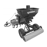
ROTO-HOG™ POWER TILLER - OPTIONAL ACCESSORIES
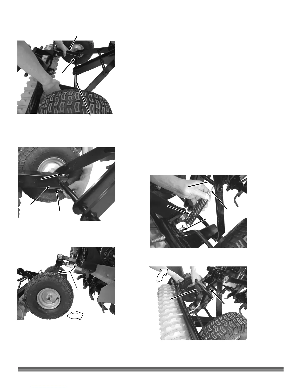
4. Slide the Slotted Tubes of the Frame Assembly onto the Lower Wheel Axle
of the Tiller until the Axle is seated into the slot base of both Slotted Tubes
(Figure 21).
5. Insert the Clevis Pins into the holes at the ends of both Slotted Tubes from
the top and secure the Clevis Pins with Hairpin Clips (Figure 22).
6. Use the ROTO-HOG Control Box to Raise the Tiller Tines to their uppermost
position (Figure 23).
NOTE: The “S” Hooks have a large and small end. The large end is for the Support
Rod and the small ends are for the Springs to attach to in the next step.
7. Place the small ends of the “S” Hooks onto the Springs and hook the
Springs to the Eye Bolts (Figure 24).
8. Rotate the Culti-packer up towards the Wheel Frame and hook the “S”
Hooks to the Support Rod on the Tiller Wheel Frame Assembly.
9. Slowly lower the Culti-packer to the ground.
10. Lift the Culti-packer as you rotate the Hook Assembly forward until the
Lower Slots of the Hook Assembly can be hooked over the Support Rod
(Figure 25).
11. The Culti-packer is now in transport mode.
Figure 21
Lower Wheel Axle of
Tiller Assembly
Slotted Tube/ Culti-packer
Frame Assembly
Slot
Figure 23
approx.
90°
Figure 25
Transport
Hook
Lower
Slot
Figure 22
Hairpin
Cli
Clevis Pin
Slotted
Tube
Figure 24
Support
Ro
“S” Hook
Spring
Eye
Bolt
 Loading...