6 DR
®
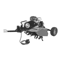
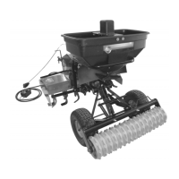
ROTO-HOG™ POWER TILLER - OPTIONAL ACCESSORIES
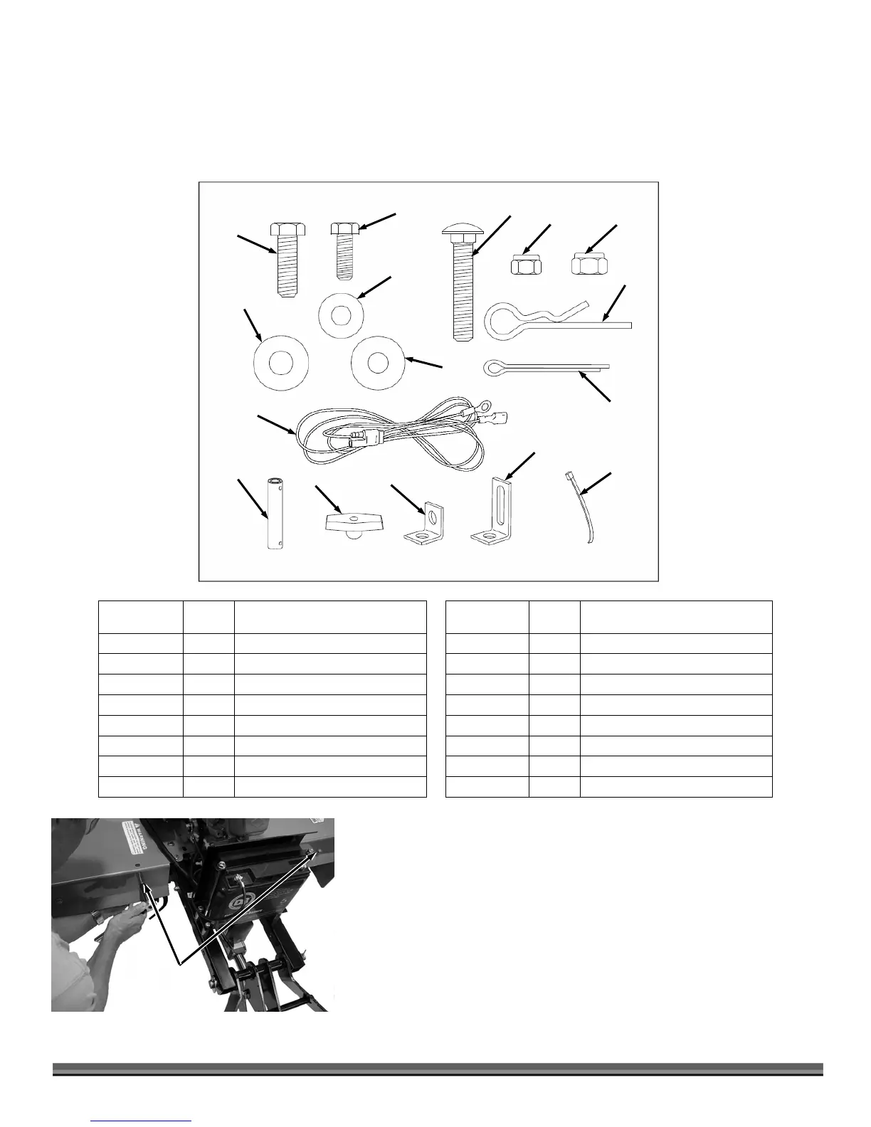
Hardware Package Contents
The item numbers on the illustration and in the table below are the same item numbers listed in the parts list and schematic
diagram in the “Parts List and Schematic Diagrams” section of chapter 7. This reference will aid in the proper location of parts as
you assemble the spreader.
Installing the DR POWER SPREADER
Tools Needed:
• 7/16" Wrench and Socket
• 1/2" Wrench and Socket
Instructions:
1. Remove two 5/16-18 X 2-1/4" Hex Head Bolts, Washers and Nylock Nuts
(1/2" Wrench) from the back face of the ROTO-HOG POWER TILLER Fender
(Figure 3).
ITEM NO. QTY. DESCRIPTION ITEM NO. QTY. DESCRIPTION
35 4 Hex Bolt, 5/16" x 1" 25 1 Hair Pin Agitator
28 2 Hex Bolt, 1/4" x 3/4" 39 3 Cotter Pin, 1/8" x 1-1/4"
21 5 Carriage Bolt, 5/16" x 1-3/4" 37 1 Impeller Coupler
7 2 Nylock Hex Nut, 1/4" 17 5 Wing Knob
26 4 Nylock Hex Nut, 5/16" 33 2 Angle Bracket
6 2 Flat Washer , 1/4" 46 1 Mounting Clamp
32 8 Flat Washer, 5/16" 41 2 Nylon Tie
5 2 Nylon Washer
48 1 Spreader Cable
21
7
26
25
39
35
28
5
6
37
17
33
46
41
32
48
Hex Head Bolts,
Washers and
Nylock Nuts
Figure 3
Tiller Fender
 Loading...