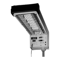
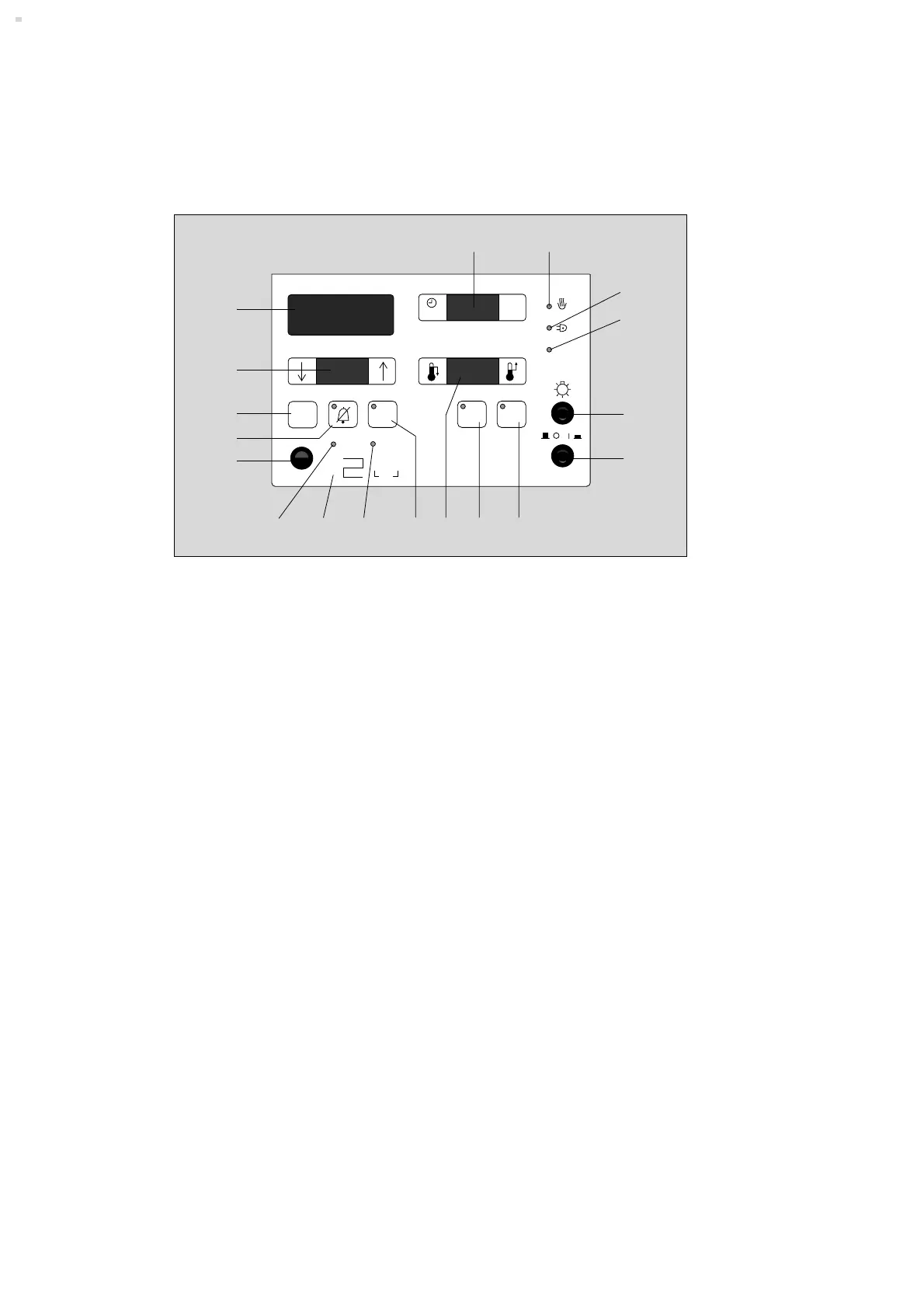
Control panel
1 Power switch
2 Lamp switch
3 Push-button for »Man« (manual) mode;
when activated, the green LED is lit.
4 Push-button for acknowledging the intermittent
alarm tone that is sounded every 15 minutes at
heater level 5 and above to remind the user to
measure the core temperature.
The yellow LED goes out after the alarm is
acknowledged.
5 Green bar-segment display for the heater output
level; one segment corresponds to a heater level
of 10% max. heater power;
To the left of the bar display:
Key for reducing the heater level.
To the right of the bar display:
Key for increasing the heater level.
6 Push-button for »Auto« (automatic) mode;
the green LED comes on when the button is
pressed = skin temperature control activated.
7 Red LED "Sensor":
comes on during skin temperature control if the
skin temperature sensor is removed or defective.
8
[
Follow the Instructions for Use of the skin
temperature control.
9 Red LED ±0,5 °C;
flashes when the measured skin temperature
deviates by more than ±0.5 °C from the set value.
10Connection for skin temperature sensor
11Push-button for muting the intermittent alarm tone for
10 minutes;
the yellow LED comes on while the intermittent tone
is muted.
12Push-button for simulating the temperature
36 ±0.1 °C (function check).
13Display for the set value of the skin temperature.
To the left of setpoint display:
Key for reducing the skin temperature setting.
To the right of setpoint display:
Key for increasing the skin temperature setting.
14Display for the actual measured skin temperature.
15Timer display.
To the left of the display:
Start key.
To the right of the display:
Stop key (1x)
Reset key (2x)
16Yellow LED OO
OO
;
lights up/flashes according to heater phases.
17Red LED NN
NN
;
lights up in the event of a power failure.
18Red LED Inop;
lights up in the event of a malfunction.
What's what
52
Auto
±0,5°C
Sensor
Inop.
°C
°C
D
Check
36°C
±0,1
min sec
Man
Stop
Reset
Start
Reset
15 min
16
17
18
2
1
3 4
15
14
13
12
10
5 7 6 9
11
8
[


 To Next Page
 Loading...