EasyManua.ls Logo

DRAKE MEQ1000B User Manual

DRAKE MEQ1000B
35 pages
To Next Page IconTo Next Page
Page #1 background imageLoading...
Page #1 background image
Rev: 120415 / 651238000A
© 2015 R.L. Drake Holdings, LLC.
MEQ1000B Hybrid QAM Modulator
Multi-solution Edge QAM Platform
INSTRUCTION MANUAL
Model Item # Description
MEQ1000B 1002511B Multiplexing QAM Modulator w/ dual input bays
Program Acquisition Modules
DTD1000A 1002512A Digital Tuner and Demodulator Module - 8VSB/QAM
SDM1000 1002576 Satellite Tuner and Demodulator Module - QPSK/8PSK
IPI1000 1002608 IP Input Module – GigE
ASII 1002397 ASI Input Module w/ loop thru
MPEG Encoder Modules
SDE24A 1002514A SD Dual Video Encoder Module
HDE24A 1002515A HD Video Encoder Module
SDI24A 1002516A SDI Video Encoder Module
Question and Answer IconNeed help?

Do you have a question about the DRAKE MEQ1000B and is the answer not in the manual?

DRAKE MEQ1000B Specifications

General IconGeneral
TypeQAM Modulator
OutputRF
Output Impedance75Ω
Input ConnectorBNC
MER>40 dB
BER<1.0E-9
Output ConnectorF-female
Operating Temperature0 to 50°C
Storage Temperature-20 to 70°C

Summary

Caution Statements

General Warnings

Presents warnings regarding fire, electrical shock, rain, moisture, and opening the product.

Important Safety Instructions

Operational Safety Guidelines

Covers general operating, cleaning, and safety guidelines for product use.

Installation and Environmental Safety

Details safety concerning antenna grounding, power cords, lightning, and product installation.

Specifications

MEQ1000B Unit Specifications

Details QAM modulator and physical specifications for the main unit.

Installation and Power-Up

Unpacking and Installation Procedures

Details items included in the box and basic installation requirements.

Power-Up Sequence

Instructions for powering on the unit.

General Description and Features

MEQ1000B Product Overview

Provides a general description of the hybrid QAM modulator and its capabilities.

Front and Rear Panel Operation

Front Panel Controls and Indicators

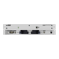
Details the Ethernet Control, IP Reset Button, Status LED, and Power indicators.

Rear Panel Connectors and Ports

Describes the RF Output, EAS Input, Module Input Slots, and ASI Output.

Login and Network Access

Ethernet Connection and IP Configuration

Guides users on configuring computer IP address for accessing the unit via Ethernet.

Web Interface Login Procedure

Explains how to access the web interface and use default credentials.

Multiplex Tab Settings

Multiplex Setup and Program Control

Details settings for enabling multiplex, slot offsets, and program numbers.

Multiplex Tab - Table Generation and Channel Mapping

Channels Tab Configuration

MPEG and Virtual Channel Number Setup

Details how to set MPEG numbers and virtual channel numbers for slots.

Output Tab Settings

QAM Output Configuration Parameters

Covers Output Mode, RF Output Level, Modulation, Interleave Mode, and Symbol Rate.

EAS/DTA Tab Configuration

EAS/DTA Control and Mode Settings

Explains EAS/DTA control, DTA control, and EAS/DTA modes.

EAS/DTA Tab - Advanced Settings

System Configuration and Logging

Admin Screen and User Management

Firmware Update Procedure

Firmware File Upload Process

Details the steps for selecting and uploading firmware files.

Service and Technical Support

Product Return Authorization Process

Outlines the RMA process for repairs and credit returns.

Customer Technical Assistance

Provides contact information for technical assistance and troubleshooting tips.

Related product manuals