Do you have a question about the DRAKE SPR-4 and is the answer not in the manual?
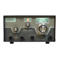
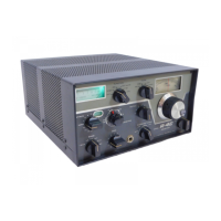
Receiver capabilities and functions.
Detailed technical specifications including frequency coverage, modes, and sensitivity.
Electrical power requirements for the receiver.
Physical dimensions and weight of the receiver.
List of semiconductor components used in the receiver.
Procedure for safely removing the unit from packaging.
Guidance on optimal placement and environment.
Information on power sources and connections.
Connecting external antennas for optimal reception.
Options for audio output via speakers.
How to connect and use headphones.
Adjusting the unit's tilt for better visibility.
Detail of the power connector.
Information about the protective fuse.
Speaker connection specifics.
Accessory port functions.
Muting function description.
Grounding terminal description.
RTTY accessory interface.
Audio input/output jack description.
Operation of the dial illumination.
Description of the antenna input jack.
Guide to installing crystals.
Explanation of front panel controls.
Step-by-step usage example.
Process for calibrating the tuning dial.
Explanation of the loop amplifier circuit.
Explanation of the RF amplifier circuit.
Explanation of the first mixer circuit.
Explanation of the premixer circuit.
Explanation of the second mixer circuit.
Description of the IF stage.
Overview of signal detection methods.
Details on AM signal detection.
Details on CW/SSB detection.
Explanation of the audio amplifier circuit.
Explanation of the Automatic Volume Control system.
Description of the muting function.
Explanation of the S-meter function.
Instructions for accessing internal components.
Guidance for diagnosing and fixing issues.
General procedure and required equipment.
Specific alignment steps for filters.
Specific alignment steps for the 5645 kHz IF.
Alignment of preselector and injection stages.
Procedure for aligning the notch filter.
Steps to calibrate the S-meter.
Description, installation, operation, and service of the SCC-4.
Description, installation, operation, and service of the 5-NB.
Description, installation, operation, and service of the RY-4.
Description, installation, operation, and service of the TA-4.
Details on modifying the SPR-4 AVC system.
Voltage charts and service info for accessories.