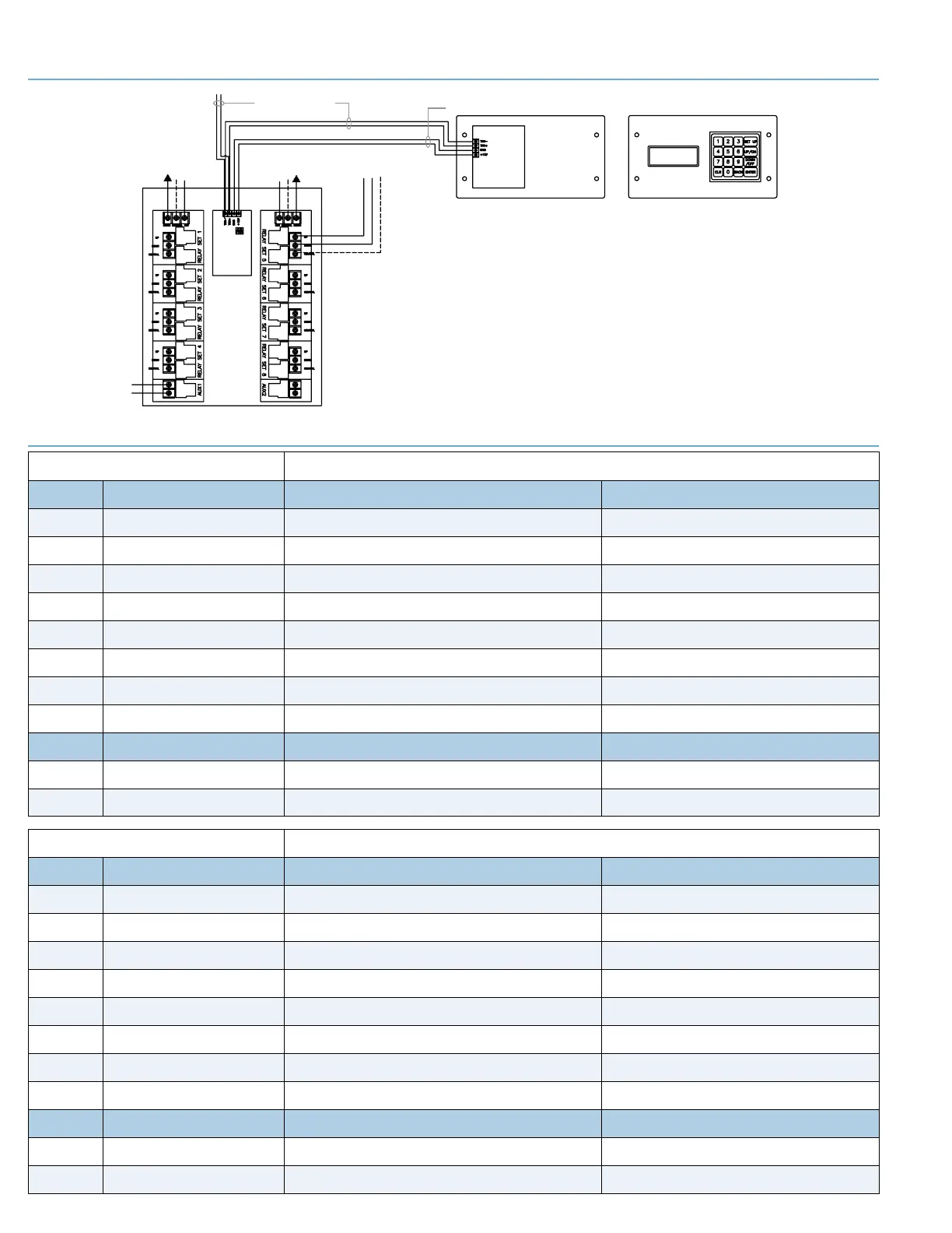
Relay Panels
(TRX- and TRX+)
18 Ga. Shielded
Two Conductor Cable
120V From
Power Supply
120V From
Power Supply
To Device
Up Down Neutral
Back of Control Panel
Requires 85/8" #4-½" x 2½"
Electrical Box (RACO #942
or equivalent)
Front of Control Panel
Touch Pad should be mounted
in location to allow view of
equipment to be operated.
Touch any
key to start
(
2) Power feeds, per Relay Panel required.
Note: (2) motors, per circuit, may be simultaneously operated.
Circuit and wire sizeto be determined based on motor type andquantity.
Max. 120 volt, 30 amp, single phase.
ux Relays
30 Amps,
220 Volt Max.
IN
OUT
Two Conductor Cable
Section 8 - Relay Assignment Worksheets (Photocopy as required to match your network requirements)
BOX #____________________
Dipswitch Setting (on/off) ds #1_____ ds #2_____ ds #3_____ ds #4_____
RELAY SET DEVICE # (1-8, 11-18, 21-28 etc.) COMPONENT DESCRIPTION (north end main court unit, etc) COMPONENT NAME (Backstop #1, Curtain #2, etc.)
1
2
3
4
5
6
7
8
DEVICE # (9-10, 19-20, 29-30 etc.) COMPONENT DESCRIPTION (north end main court unit, etc) COMPONENT NAME (Lights, PA System, etc.)
AUX 1
AUX 2
Section 7 - Wiring Diagram Keypad
BOX #____________________
Dipswitch Setting (on/off) ds #1_____ ds #2_____ ds #3_____ ds #4_____
RELAY SET DEVICE # (1-8, 11-18, 21-28 etc.) COMPONENT DESCRIPTION (north end main court unit, etc) COMPONENT NAME (Backstop #1, Curtain #2, etc.)
1
2
3
4
5
6
7
8
DEVICE # (9-10, 19-20, 29-30 etc.) COMPONENT DESCRIPTION (north end main court unit, etc) COMPONENT NAME (Lights, PA System, etc.)
AUX 1
AUX 2
page 4 of 4
E Z-Pad Pl u s
®
 Loading...