Low Voltage Control Wiring Diagrams for All Draper Products
Copyright ©2011 Draper Inc. Form LVC-Wiring_Inst11 Printed in the U.S.A.
Revelation ....................................... Page 1
Micro Projector Lift .......................... Page 1
AeroLift 25 ...................................... Page 2
AeroLift 50/150 ............................... Page 2
LCD Lift .......................................... Page 3
Single Screen ................................. Page 4
Multiple Screens ............................. Page 4
If you encounter any diffi culties installing or ser vic ing your
Low Voltage Control, call your dealer or contact Draper, Inc.,
Spiceland, In di ana, 765-987-7999, or fax 765-987-7142.
LVC-III—Revelation
Wiring Diagram
LVC-III—Micro Projector Lift
Wiring Diagram
Motor
Black (Down)
Dashed wiring
by electrician
Location of key
operated on-off
switch if furnished
N
O
To 110-120v
Line
White (Common)
Red (Up)
Green (Ground)
Green (Ground)
White
Black
N
DN
UP
To 110 -120V AC Line
3 Button Wall Switch
DOWN - Black
COM - White
UP - Red
White- Neutral (Common) to lift & 110-120V AC
Brown-to lift (directional)
Red-to lift (directional)
Yellow-to 110-120V AC
Black-to 110-120V AC
Green-Ground
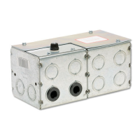
Eye Port for IR Eye, RF Receiver or LED
Switch. If more than one of these three is
used with one LVC-III, a splitter is required.
Aux Port for connecting additional LVC-III
modules (up to six-connect from Aux to Eye)
Low voltage wiring
by others
YW
PCB 1
T 1
110 VAC SUPPLY
PROJECTOR OUTLET
Wiring by Electrician
GND
N
50 - 60 HZ
L1
GN
BK
WH
F3
CB1B
8
BK
109
RD
BK
BK
BK
6745321
F1
F2
YW
YW
C2
BK
RD
BE
YW
D1
BK
DOWN
ALL WIRES 18 AWG. UNLESS OTHERWISE SPECIFIED.
BE
BK
1098765432 1
CB1A
BK
WH
BK
BE
C1
BK
RD
BE
BE
BE
WH
DOWN LIMIT SW
UP LIMIT SW
RD
RD
BE
BE
BE
WH
BK
BE
RD
BE
RD
WH
4321765
12 V
CR 2
CR 1
BK
BE
BE
RD
BE
BE
BE
RD
UP
RD
BK
BK
MOTOR
GN
RD
BK
TB 2
BK
RD
GN
1098
OR
BN
VIDEO INTERFACE
CONTROL
BK
WH
GN
YL
BN
RD
WH
14 AWG
WH
WH
14 AWG
WH
GN 14 AWG
14 AWG
BK
11 1210897
TB 1
654321
Transform 115V/12V@1Amp 50/60Hz
110V .03hp 50-60hz. 200Lb-in. 1.1rpm
Fuse 1Amp AGC 250 Vac
T1
MOTOR
F3
Relay, Coil-12Vac, 2PDT 230Vac 10Amp
Relay, Coil-12Vac, 2PDT 230Vac 10Amp
COMPONENT SPECIFICATIONS
Diode NTE125002B
Capacitor 100mfd 35 Vac
Capacitor 10mfd +/- 370 Vac
Fuse 7Amp AGC 250 Vac
Fuse 1Amp AGC 250 Vac
CR2
F2
F1
D1
CR1
C2
C1
SYM
Wiring by others
Eye Port for IR Eye, RF Receiver or LED
Switch. If more than one of these three is
used with one LVC-III, a splitter is required.
3 Button Wall Switch
DOWN - Black
COM - White
UP - Red
Red
Brown
Yellow
Green
White
Black
Aux Port for connecting additional
LVC-III modules (up to six total-
connect from Aux to Eye).
®