Do you have a question about the Dresser MAR50 and is the answer not in the manual?
Steps for adjusting cams for MAR8 models with square cam adjustment.
Steps for adjusting cams for MAR/DCR8RH models with round cam adjustment.
Cam adjustment procedure for older MAR/DCR10, 50, 90 part-turn models.
Cam adjustment procedure for newer MAR/DCR10, 50, 90 part-turn models.
Cam adjustment procedure for MAR/DCR10, 50, 90 multi-turn models.
Cam adjustment for new style part-turn models in Groups 12/16.
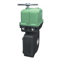
The MAR/DCR Series Groups 3, 9, 12, 16, 25 & 40 Actuators are mechanical devices designed for controlling valve operations, ensuring safety and precision in industrial applications. These actuators are built with a focus on reliable performance and ease of maintenance, making them suitable for various environments.
The primary function of these actuators is to provide automated control over valve positions, enabling them to open or close as required. They are designed for both part-turn and multi-turn applications, depending on the specific model. The actuators can be operated manually or electrically, offering flexibility in control.
For manual operation, different models employ distinct mechanisms. Models MA8 and MAR8 utilize an open-end wrench on a hex stock-coupling adapter, with an indicator on the output shaft to check position and direction of rotation. Users are cautioned against turning beyond normal open/close travel. Models MAR10, 50, and 90 feature a black declutching knob (A). To operate manually, this knob is pulled up and held, while the shaft is gently rocked with a wrench to disengage it. Once disengaged, the shaft can be rotated to the desired position, guided by arrows. The actuator automatically re-engages when the knob is released and electrical power is applied. Again, turning beyond normal travel limits is advised against. Larger models, MAR100, 120, 160, 250, 800, 1600, and 4000, incorporate a handwheel. Manual operation involves depressing and slowly rotating the handwheel until a detent is felt, indicating engagement. The handwheel is then turned in the desired direction, with markings on the wheel and an indicator on the output shaft guiding the position. As with other models, over-travel is to be avoided. A key safety feature in these larger models is an integral cut-off switch that activates when the handwheel is depressed for manual operation, preventing injury from unexpected electrical power restoration. This switch automatically resets when the handwheel is returned to its raised position, restoring electrical operation.
The actuators are designed to be installed on a valve, typically in the open position. Proper alignment between the actuator and valve shafts is crucial for correct operation. The direction of rotation (clockwise or counter-clockwise) is defined as viewed from above the top of the actuator output shaft. Once mounted, the actuator is centered on the valve stem by tightening bolts evenly. It is often beneficial to manually cycle the actuator with slightly loose mounting bolts to allow the unit to self-center.
Electrical operation is enabled after wiring the actuator according to the provided diagram. The wiring diagram is drawn with the actuator in the open position, and #18AWG stranded wire or better is recommended for field hook-up.
A critical aspect of using these actuators involves cam adjustment, which sets the travel limits for both open (counter-clockwise) and close (clockwise) directions. Different groups of models have specific cam adjustment procedures.
For Square Group 3: MAR8 Models, open travel adjustment involves loosening the setscrew on Cam 1 (and Cam 3 for auxiliary switches), rotating the cam(s) counter-clockwise away from the switch, manually moving the actuator to the full open position, then rotating Cam 1 (and Cam 3) clockwise until it engages the switch roller and the switch "breaks" (indicated by a light click). The setscrew on Cam 1 is then tightened. If auxiliary switches are present, Cam 3 is rotated about 2 degrees clockwise and its setscrew tightened to ensure Switch 3 "makes" at the full open position. Close travel adjustment follows a similar process with Cam 2 (and Cam 4 for auxiliary switches), rotating them clockwise away from the switch, moving the actuator to the full close position, then rotating Cam 2 (and Cam 4) counter-clockwise until the switch "breaks." Cam 4 is then adjusted if auxiliary switches are present.
Round Group 3: MAR/DCR8RH Models follow a similar cam adjustment procedure, ensuring the cams are rotated away from the switch, the actuator is moved to the full open/close position, and the cams are rotated back until the switch "breaks." Auxiliary switches are adjusted by rotating their respective cams slightly further.
Group 9: MAR/DCR10, 50, 90—Part Turn Models (old style) utilize Cam 7 (and Cam 9 for auxiliary switches) for open travel and Cam 2 (and Cam 4 for auxiliary switches) for close travel. The procedure involves loosening setscrews, rotating cams away from the switch, manually moving the actuator to the full open/close position, rotating cams until the switch "breaks," and then tightening setscrews. If travel control is not achieved, micro-adjustment cams can be repositioned by loosening pivot and micro-adjustment screws, swinging the switch outward or inward relative to the main cam, and then re-tightening.
Group 9: MAR/DCR10, 50, 90—Part Turn Models (new style) and Multi-Turn Models have their own specific cam adjustment sequences, involving Cams 2 and 4 for open travel and Cams 1 and 3 for close travel in part-turn models, and Cams 1 and 3 for open travel and Cams 2 and 4 for close travel in multi-turn models. The process remains consistent: loosen, rotate away, move actuator, rotate to "break," and tighten. Multi-turn models also require noting the direction of cam rotation.
Groups 12/16: MAR100, 120, 160, 250 & 800; DCR100, 160, 250 & 800—Part Turn Models (new style) use Cams 2 and 4 for open travel and Cams 1 and 3 for close travel, following the standard adjustment steps. Old style models in these groups use Cams 7, 9, and 11 for open travel and Cams 2, 4, and 6 for close travel, with a similar adjustment logic. Micro-adjustment cam repositioning is also available for these models if needed.
Groups 25 & 40: MAR1600 & 4000—Part Turn Models have a more involved adjustment process, including manual stop bolts on the worm gear assembly. For open travel, setscrews on Cam 1 (and Cam 3) are loosened, cams rotated counter-clockwise, manual stop bolts loosened, actuator moved to full open, then Cam 1 (and Cam 3) rotated clockwise until the switch "breaks." The Open Stop Bolt is then rotated clockwise until it "bottoms out" and then one full turn counter-clockwise. Close travel follows a similar procedure with Cam 8 (and Cam 10) and the Close Stop Bolt. Micro-adjustment cam repositioning is also detailed for these models.
Group 12 Multi-Turn Models: MAR120 & 250–5, 8, 13 & 50 Turn Models and MAR120 & 250-18 & 26 Turn Models also have specific cam adjustment procedures, utilizing Cams 8 and 10 for open travel and Cams 1 and 3 for close travel, with the option for micro-adjustment if necessary.
Throughout all cam adjustment procedures, the cover is replaced and flange bolts tightened, and any manual declutching knobs or handwheels are reinstalled and tightened.
The actuators are designed for minimal maintenance. The gear case section is adequately lubricated at the factory, and this lubricant typically does not need changing. However, if disassembly occurs, Lubriplate Mag-1 is recommended for refilling.
A thermal protective device is integrated into every motor to prevent damage from overheating. This device automatically resets once the motor temperature returns to a safe level. All RCS motors are equipped with Class B insulation.
For storage, the Electripowr actuator should be kept in a clean, dry, temperature-controlled building, protected from weather. Precautions are necessary to prevent condensation, such as installing and energizing internal heaters if external temperature and humidity control are insufficient. Actuators should be stored off the floor on pallets and covered with an unsealed dust protector.
Troubleshooting guidance is provided for common issues:
The manual emphasizes that all Electripowr actuators have built-in thermal overload motor protectors that automatically reset when the motor temperature drops to a safe level, addressing issues caused by any of the above conditions.
For ordering spare or replacement parts, users are directed to use the parts drawings and lists provided in the manual, noting the part number and name of the part. To obtain replacement parts, information from the actuator nameplate, including serial number, model number, and voltage, must be submitted.
A crucial safety warning is consistently highlighted: "To prevent ignition of hazardous atmospheres, do not remove actuator cover while circuits are live." This underscores the importance of safety procedures during installation, adjustment, and maintenance.
| Brand | Dresser |
|---|---|
| Model | MAR50 |
| Category | Controller |
| Language | English |