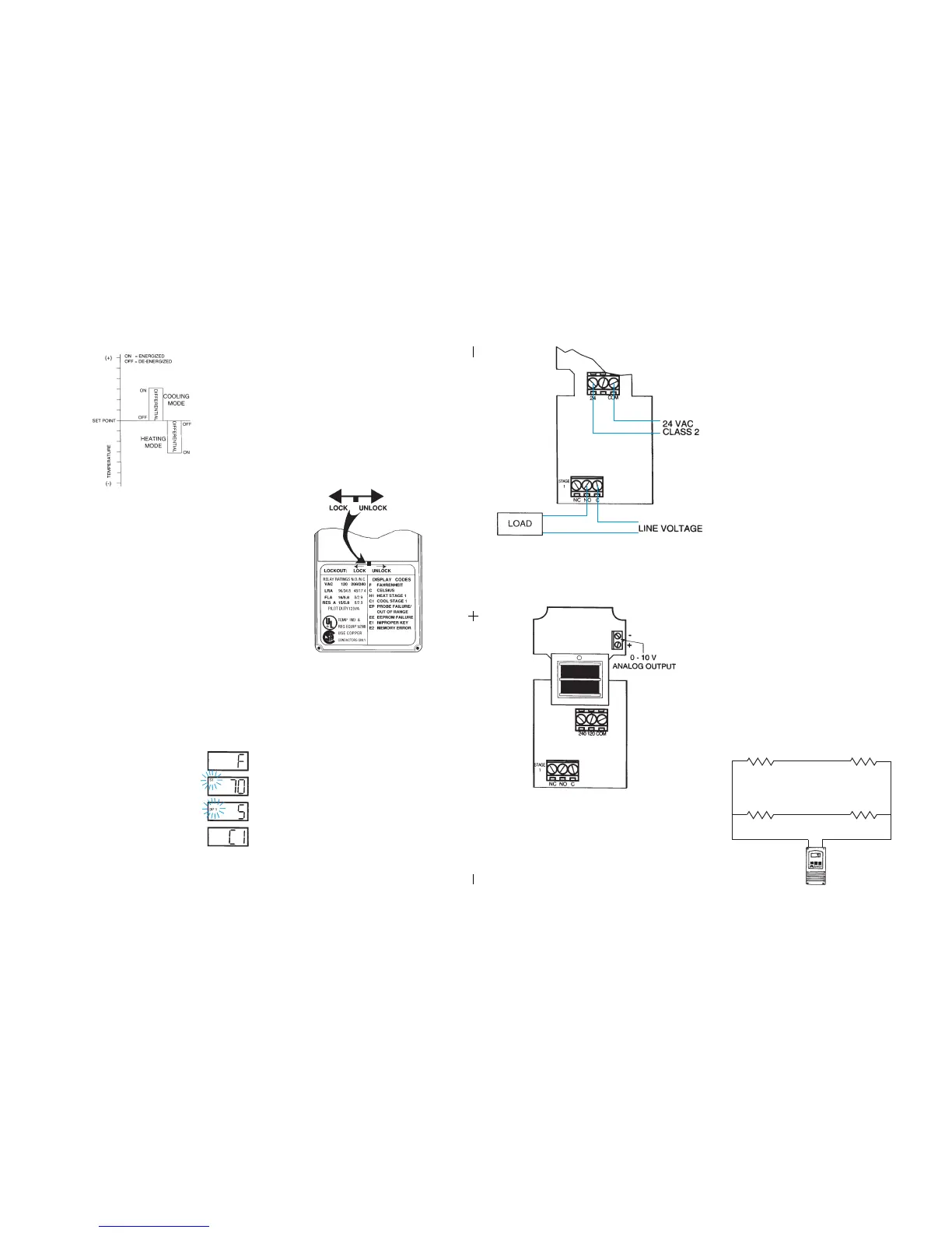
Figure 7: Typical Wiring Diagram for 24 VAC Power Input and
Line Voltage Switching.
Figure 8: 0-10 V Analog Output Located on Power (Lower) Circuit Board.
FIELD REPAIRS
Field calibrating or repairs to the ETC control must not be attempted. Sensors
and replacement controls are available through Ranco wholesalers.
SENSOR MOUNTING
For space sensing, mount the sensor where it will be unaffected
by heat/cool discharge or radiated heat sources. Spot sensing
requires the sensor to be in good contact with the surface being
sensed. The sensor can be inserted in a bulb well for immersion
sensing.
TEMPERATURE AVERAGING
ETC CONTROL
EXTENDING SENSOR
CAUTION: Sensor wiring splices may be made external from the
control. DO NOT attempt to unsolder the sensor at the control
circuit board!
CAUTION: Disconnect power to control before wiring to avoid
possible electrical shock or damage to the controller.
Additional cable can be spliced to the sensor cable to increase the
length beyond the standard 8 feet. It can be extended up to 400
feet. The cable should be at least 22 AWG or larger to keep
additional resistance to a minimum.
All splices and wire lengths added to the sensor cable should be
made according to acceptable wiring practices and should con-
form to the National Electrical Code and local regulations. Use
copper conductors only. Shielded cable is not required.
Checkout Procedure
1. Before applying power, make sure installation and wiring
connections are correct.
2. Apply power to the control and observe one or more cycles
of operation.
3. If performance indicates a problem, check sensor
resistance to determine if sensor or control is at fault.
4. To check sensor resistance, disconnect sensor and
measure the resistance across the leads while measuring
temperature at the sensor.
(4) Sensors wired in series/parallel for temperature averaging.
SENSOR
SENSOR
5
Step 1- To start programming, press the SET key once to access the
Fahrenheit/Celsius mode. The display will show the current
status, either F for degrees Fahrenheit or C for degrees Celsius.
Then press either the up or down arrow key to toggle
between the F or C designation.
Step 4- Press the SET key again to access the cooling or heating mode.
The LCD will display the current mode, either C1 for cooling or
H1 for heating. Then press either the up or down key to
toggle between the C1 or H1 designation. Press the SET key
once more and programming is complete.
Step 3- Press the SET key again to access the differential. The LCD will
display the current differential and the DIF 1 annunciator will be
blinking on and off to indicate that the control is in the differential
mode. Then press either the up key to increase or the down
key to decrease the differential to the desired setting.
Step 2- Press the SET key again to access the setpoint. The LCD
will display the current setpoint and the S1 annunciator will be
blinking on and off to indicate that the control is in the setpoint
mode. Then press either the up key to increase or the down
key to decrease the setpoint to the desired temperature.
Step Annunciator Description Display
1 F or C Fahrenheit or Celsius Scale
2 S1 (blinking) Setpoint Temperature
3 DIF 1 (blinking) Differential Temperature
4 C1/H1 Cooling or Heating Mode
Figure 1: Setpoint and Differential Settings. Diagram indicates relay
on and off points in either the heating or cooling modes.
TROUBLESHOOTING ERROR MESSAGES
All control settings are retained in non-volatile memory if power to ETC is
interrupted for any reason. Re-programming is not necessary after power
outages or disconnects unless different control settings are required.
Lockout Switch
The ETC is provided with a lockout switch to prevent tampering by unautho-
rized personnel. When placed in the LOCK position, the keypad is disabled
and no changes to the settings can be made. When placed in the UNLOCK
position, the keypad will function normally.
Display Messages
Programming Steps and Display
The ETC can be programmed in four simple steps using the LCD display and
the three keys on the face of the control.
NOTE: The ETC will automatically end programming if no keys are
depressed for a period of thirty seconds. Any settings that have been input
to the control will be accepted at that point.
To access the lockout switch, disconnect the power supply and open the
control. The switch is located on the inside cover about 2 inches above the
bottom. (see Figure 2). To disable the keypad, slide the switch to the left
LOCK position. To enable the keypad, slide the switch to the right
UNLOCK position. All ETC controls are shipped with this switch in the
UNLOCK position.
Figure 2: Lockout Switch
EP - Appears when the probe is open, shorted or sensing a tempera-
ture that is out of range.
To correct: Check to see if the sensed temperature is out of
range. If not, check for probe damage by comparing it to a
known ambient temperature between -30°F and 220°F. Replace
the probe if necessary.
EE - Appears if the EEPROM data has been corrupted.
To correct: This condition cannot be field repaired. Replace
the control.
CL - Appears if calibration mode has been entered.
To correct: Remove power to the control for at least five
seconds. Reapply power. If the CL message still appears,
replace the control.
➡
➡
➡
➡
➡
➡
➡
➡
E2 - Appears if the control settings are not properly stored in memory.
To correct: Check all settings and correct if necessary.
➡
➡
E1 - Appears when either the up or down key is pressed when
not in the programming mode.
To correct: If the E1 message appears even when no keys are
being pressed, replace the control.
2
SENSOR SENSOR
Figure 9:
 Loading...