1
LE LI
-
O1
M
O2 O3 O4
+OC
AS
M
L1 L2 L3 L4 +12V-
LOCK
OPEN
44
5
17
3
2
6
16
9
10
8
11
13
12
15
14
4
12 13
TAMPER
9
PGM3
8
PGM2
19 20
+
DC IN
-
11
AUX+
16
Z2
17
Z3
15
Z1
14
COM
10
PGM4
7
PGM1
6
COM
4
T1
5
R1
2
TIP
3
RNG
1
18
Z4
JP3
JP3
tie wrap
OFF ON
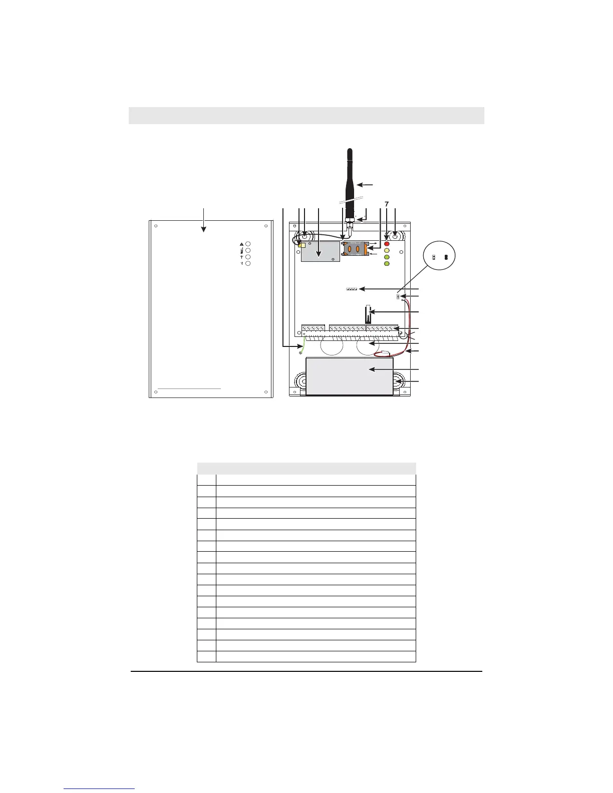
All circuits are classified for UL installations as Power Limited/Class II Power Limited except for the bat-
tery leads which are not power limited. Do not route any wiring over circuit boards. Maintain at least 1”
(25.4mm) separation. A minimum 1/4” (6.4mm) of separation must be maintained at all points between
Power Limited wiring and all other non-Power Limited wiring. Route wires as indicated above.
3G3070
NOTE: For UL/ULC installa-
tions, connections between
the alarm control panel out-
puts (telephone interface
Tip/Ring, output relay con-
tacts) and 3G3070 inputs
(Tip/Ring, Z1-Z4) shall be
run in a mechanical protec-
tive conduit within 20ft (6m)
of one another and in the
same room.