Table 1: Recommended baud rate settings per cable length:
* Cable capacitance 50pF/ft
Table 2: Status Reporting via LED
Baud Rate Cable Length *
9600 98' (30m)
19200 50' (15.2m)
38400 25' (7.6m)
57600 20' (6m)
115200 8' (2.4m)
LED Status
Off Module is not powered
Solid Module is powered but communication
with panel is not initiated from start up
Flashing every ½
second
Module is powered and is receiving/sending
data with panel
Flashes 2 seconds off and
½ second on
Module is powered but there is a Trouble
with the Keybus connection
Tableau 1: Ajustements recommandés du taux de bauds par
longueur de câble :
* Capacité du câble 50pF/m
Tableau 2: Rapports de status par LED
Taux de Bauds Longueur du câble *
9600 30 m (98’)
19200 15 m (50’)
38400 7,5 m (25’)
57600 6 m (20’)
115200 2,4 m (8’)
LED Status
Débranché Le module n’est pas alimenté
Solide Le module est alimenté mais la
communication avec le tableau n’est pas
initialisée depuis l’initialisation.
Clignotant à chaque ½
seconde
Le module est alimenté et reçoit/transmet
des données avec le tableau
Il clignote avec la
fréquence de 2 secondes
éteint et ½ seconde allumé
Le module est alimenté mais il y a un
Problème avec le raccord Keybus
Tabla 1: Ajustes recomendados de la tasa de baudios por largo
de cable:
* Capacidad del cable 50pF/m
Tabla 2: Informes del Status a través del LED
Tasa de Baudios Largo del Cable *
9600 30 m (98’)
19200 15 m (50’)
38400 7,5 m (25’)
57600 6 m (20’)
115200 2,4 m (8’)
LED Status
Apagado El módulo no está alimentado
Sólido El módulo está siendo alimentado, pero la
comunicación con el panel no es iniciada
desde la iniciación
Intermitente a cada ½
segundo
El módulo está siendo alimentado y está
recibiendo / transmitiendo datos con el
panel
Se pone intermitente con la
frecuencia de 2 segundos
apagado y ½ segundo
encendido
El módulo está siendo alimentado, pero
hay un Problema con la conexión Keybus
©2006 Digital Security Controls Toronto, Canada • www.dsc.com
Tech. Support/Centre d’aide technique/Líneas Tech:1-800-387-3630 (Canada & U.S.), 905-760-3036
Printed in Canada / Imprimé au Canada / Impreso en Canadá
FCC COMPLIANCE STATEMENT
CAUTION: Changes or modifications not expressly approved by Digital Security Con-
trols could void your authority to use this equipment.
This equipment generates and uses radio frequency energy and if not installed and
used properly, in strict accordance with the manufacturer's instructions, may cause
interference to radio and television reception. It has been type tested and found to
comply with the limits for Class B device in accordance with the specifications in
Subpart "B" of Part 15 of FCC Rules, which are designed to provide reasonable pro-
tection against such interference in any residential installation. However, there is no
guarantee that interference will not occur in a particular installation. If this equip-
ment does cause interference to television or radio reception, which can be deter-
mined by turning the equipment off and on, the user is encouraged to try to correct
the interference by one or more of the following measures:
- Re-orient the receiving antenna
- Relocate the alarm control with respect to the receiver
- Move the alarm control away from the receiver
- Connect the alarm control into a different outlet so that alarm control and receiver
are on different circuits.
If necessary, the user should consult the dealer or an experienced radio/television
technician for additional suggestions. The user may find the following booklet pre-
pared by the FCC useful: "How to Identify and Resolve Radio/Television Interfer-
ence Problems". This booklet is available from the U.S. Government Printing
Office, Washington D.C. 20402, Stock # 004-000-00345-4.
IC STATEMENT
This Class B digital apparatus meets all requirements of the ICES-003.
Cet appareil numérique de la classe B respecte toutes les exigences du ICES-003.
29007302R002
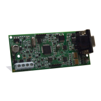
RED BLK YEL GRN
RS-232
To Application
To Panel
V
ers le Tableau
Al Panel
DB9
LED
Vers l’Application
a aplicación
Figure A
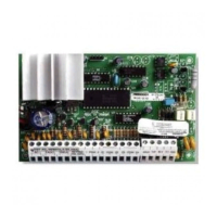
Ferrite
(DSC PN 10000054)
Panel
IT-100
Keybus Connection
Connexion de keybus
Conexión del keybus
Keybus Wires (loop 2 times)
Fils de keybus (boucle 2 fois)
Alambres del keybus (lazo 2 veces)
Panneau
Install the ferrite inside the control panel as close to the IT-100 as allowable.
Installez la ferrite à l’intérieur du panneau de contrôle aussi près que permis du IT-100.
Instale la ferrita dentro del panel de control lo más cerca posible del IT-100.
Figure B
 Loading...