On control panels with software versions 2.X and lower, the PC5108
v2.0 will operate in two groups of four zones.
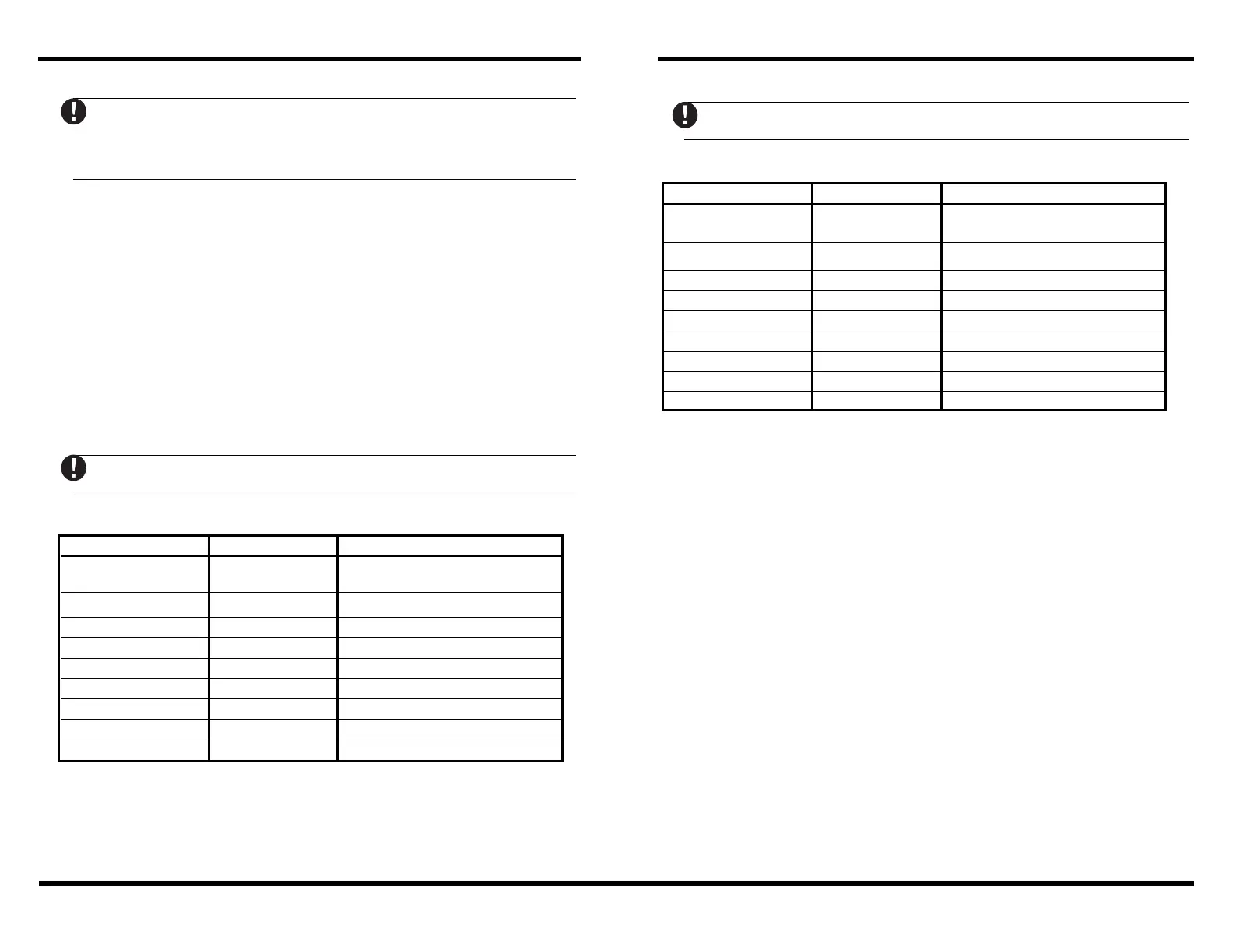
For control panels V2.x and lower, please refer to the jumper settings below…
Expander Zones Jumpers System Zones Assigned
Group A (Zones 1-4) J1 J2 J3
Group B (Zones 5-8) J4 J5 J6
ON ON ON Zones Disabled
OFF ON ON Zones Disabled
ON OFF ON Zones 9 - 12
OFF OFF ON Zones 13 - 16
ON ON OFF Zones 17 - 20
OFF ON OFF Zones 21 - 24
ON OFF OFF Zones 25 - 28
OFF OFF OFF Zones 29 - 32
To Add Hardwired Zones to a Control Panel
1. Connect module to the Keybus (with the panel powered down).
2. Set the jumpers on the module.
3. Power up the system.
4. Enter section [902] and wait 1 minute.
5. Enter section [903] to verify that the module is supervised.
6. Define the zones in sections [002]-[004], [109]-[164] for PC5020.
7. Add the zones to the appropriate partition in sections [202]-[265].
There is a built-in tamper switch on the expander module located in
the top left corner of the circuit board. If the cabinet in which the
PC5108 Zone Expander is mounted has the hardware required to
depress this tamper switch, DO NOT connect anything to the TAM
terminal.
VAUXVAUX
VAUXVAUX
VAUX - Used to provide power for devices. Maximum current draw is not to
exceed 100 mA. Connect the positive lead of powered devices to VAUX and the
negative to BLK or any COM terminal.
KEYBUSKEYBUS
KEYBUSKEYBUS
KEYBUS - The 4 wire KEYBUS connection is used by the panel to communicate
with the module. Connect the RED, BLK, YEL and GRN terminals to the KEYBUS
terminals on the PC5010, PC5015 & PC5020 main control.
Z1 to Z8Z1 to Z8
Z1 to Z8Z1 to Z8
Z1 to Z8 - Wire the zones according to the description found in the control
panel
Installation Manual
.
Jumper Settings
The PC5108 module can be used to add up to 8 additional hardwired zones to
the PC5010, PC5015, or PC5020 control panel (see
Installation Manual
for
complete installation instructions).
Jumpers
Jumpers are used to determine which zones will be assigned to the expander.
On control panels with software versions 3.X and higher, the PC5108
v2.0 will operate in a single group of eight zones.
For control panels V3.x and higher, please refer to the jumper settings below…
Expander Zones Jumpers System Zones Assigned
Group A (Zones 1-8) J1 J2 J3
Group B (Not used)
ON ON ON Zones Disabled
OFF ON ON Zones 9 - 16
ON OFF ON Zones 17 - 24
OFF OFF ON Zones 25 - 32
ON ON OFF Zones 33 - 40
OFF ON OFF Zones 41 - 48
ON OFF OFF Zones 49 - 56
OFF OFF OFF Zones 57 - 64

 Loading...