'66HULHV0RWRUL]HG*DWHV
Assembly and installation
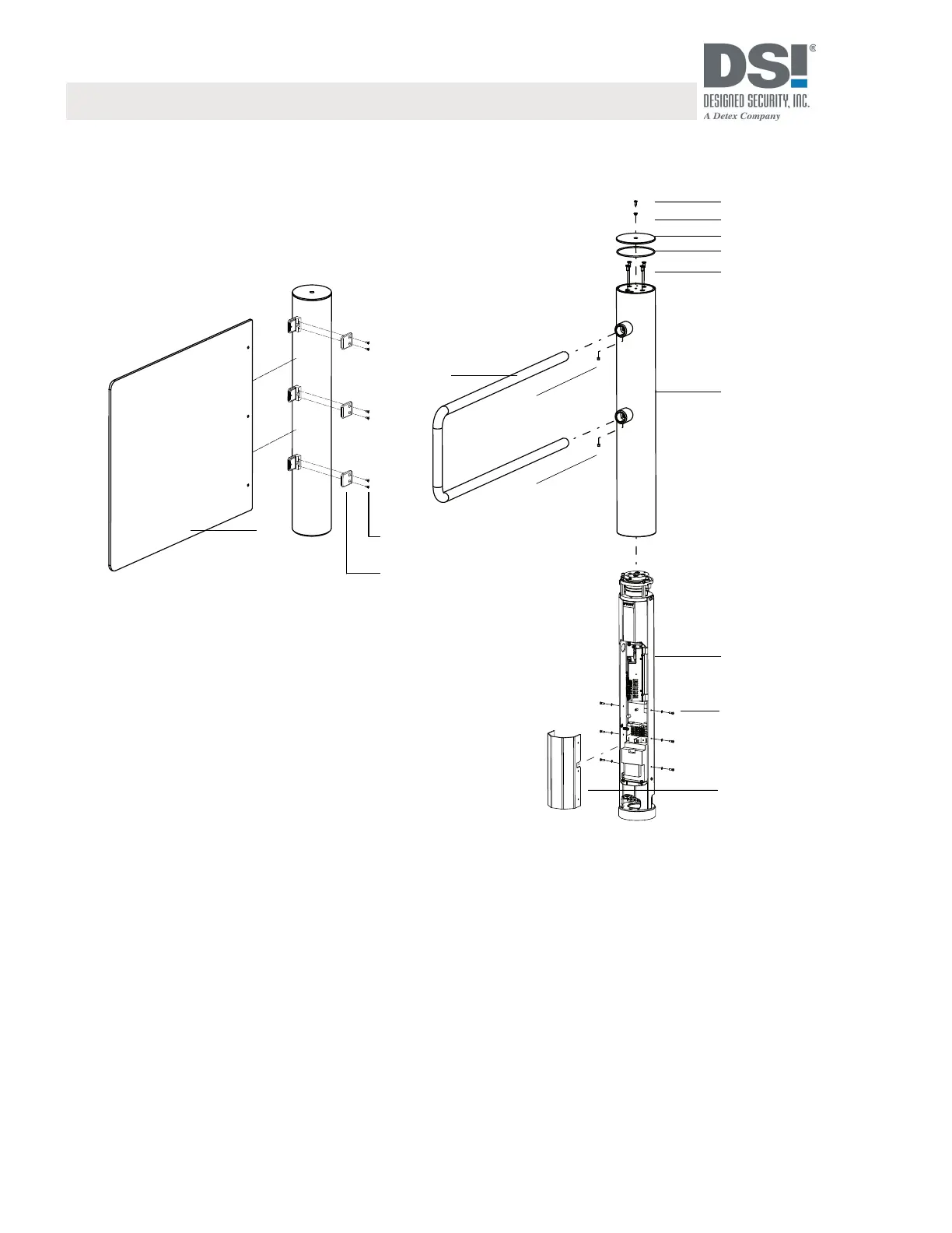
5.4 Mounting the PRWRUL]HGJDWH
[
[
Fig. 7: Mounting the PRWRUL]HGJDWH
1 Countersunk screw M6 x16
2 Isolation sleeve
3 Top cover disc
4 O-Ring
5 Countersunk screws M8 x 20
6 Outer tube
7 Edge profile (with drive, control units, transformer)
8 Disc/screws M5 x 16
9 Cover
10 Locking element in bracket version
11 Threaded pin
12 Countersunk screw M6
13 Holder for locking element
14 Locking element in wing version
Toll Free 800-272-3555 | 512-321-4426 | Fax: 512-321-9181
INS-DSMG-200702
Designed Security, Inc. - 1402 Hawthorne Street, Bastrop Texas 78602
www.dsigo.com | sales@dsigo.com
32
 Loading...