EasyManuals Logo

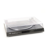
Dual CS 630 Q Service Manual

Dual CS 630 Q
12 pages
To Next Page IconTo Next Page
To Previous Page IconTo Previous Page
Page #9 background imageLoading...
Page #9 background image
E
Tonarmlift
Austausch
des
Heberbolzens
1.
Haupthebel
46
abnehmen.
Lagerteil
101
entfernen
und
Stellschiene
95
ab-
nehmen.
2.
Steuerpimpel
85
abnehmen
und
Heberbolzen
60
austauschen.
Der
Einbau
erfolgt
in
umgekehrter
Reihenfolge.
Justagepunkte
Aufsetzpunkt
Aufsetzpunktumschalter
92
in
Stellung
30
cm.
Durch
Drehen
des
auf
der
Drehplatte
98
befindlichen
Exzenters
kann
der
Aufsetzpunkt
justiert
werden.
Die
Einstellung
ist
sowohl
für
17
-cm-
sowie
für
30
-cm
-Schallplatten
wirksam.
Der
Exzenter
ist
durch
eine
Öffnung
in
der
Abdeckung
91
zugänglich.
Abstellpunkt
Der
Abstellpunkt
(Abstellbereich
Platten
0
125-115
mm)
kann
durch
geringfügiges
Biegen
der
Abstellschiene
30
verändert
werden.
Tonarmlift
Die
Lifthöhe
läßt
sich
durch
Drehen
der
Schraube
58
verändern.
Der
Abstand
zwischen
Schallplatte
und
Abtastnadel
soll
ca.
5
mm
betragen.
Tonearm
and
tonearm
bearing
DIsmantling
the
tonearm
complete
with
the
tonearm
bearing
We
recommend
the
following
procedure:
1.
Unsolder
off
the
tonearm
connections
at
the
connection
board
7.
2.
Remove
the
sleeve
86.
Disengage
the shut-off
bar
30
and
the
spring
65
on
the
segment
87.
3.
Lift
off
main
lever
46.
Hold
tonearm.
Remove
the
lock
screw
on
the
frame
56.
Remove
the
lock
screw
on
the
tonearm
support
59.
Disengage
the
tonearm
84
on
the
positioning
rau
l
95.
Remove
the
tonearm
84.
Succession
the
spring
on
the
lifting
bot
60.
Reassembly
involves
the
reverse
procedure.
Dismantling
the
tonearm
from
the
bearing
case
1.
Remove
weight
50.
Unsolder
off
the
tonearm
connections
at
the
connection
board
7.
2.
Remove
screw
82.
Remove
control
knob
81
and
washer
80.
3.
Loosen
lock
nut
52
and
remove
setscrew
51.
Remove
tonearm
84.
Changing
the
spring
casing
Remove
the
tonearm
84
from
its
bearings
53
following
the
instructions
described
above.
Remove
the
spring
case
83.
Special
attention
must
be
paid
to
ensure
that
the
coil
spring
fits
in
the
recess
of
the
bearing.
Reassemble
the
tonearm.
Adjust
the
bearing
play
es
described
below.
Adjustment
of
tonearm
bearings
The
tonearm
must
be
exactly
balance.
Both
bearings
should
have
very
rittle
or
no
play.
The
horizontal
tonearm
bearing
is
correctly
adjusted
when
the
tonearm
can
freely
slide
in
and
out
with
the
antiskating
adjustment
set
to
„0,5".
The
vertical
tonearm
bearing
is
correctly
adjusted
when
the
tonearm
freely
swings
back
into
position
atter
being
tapped.
The
play
in
the
horizontal
tonearm
bearing
can
be
adjusted
with
the
setscrew
51.
The
play
in
the
vertical
tonearm
bearing
can
be
adjusted
with
the
setscrew
54.
Cue
control
Changing
the
lift
bolt
1.
Remove
the
main
lever
46.
Remove
the
bearing
piece
101
and
the
positioning
rau
l
95.
2.
Remove
the
pin
85
and
the
lift
bot
60.
Reassembly
involves
the
reverse
procedure.
Adjustment
points
Set
down
point
Set
down
point
92
in
position
30
cm.
The
set
down
pöint
of
the
tonearm
can
be
altered
with
the
excentric
bolt
(rotary
plate
98).
The
setting
is
effective
not
only
for
17
cm
but
also
for
30
cm
records.
The
excentric
bolt
is
accessible
through
the
hole
in
the
cover
91.
Switch
off
point
The
switch
off
point
(switch
off
range
record
0
125-115
mm)
can
adjusted
by
slight
bending
the
shutt-off
rail
30.
Toneann
lift
The
lift
can
be
varied
by
tuming
the
screw
58.
The
distance
between
the
record
and
the
needle
should
be
approx.
5
mm.
Bras
de
lecture
Dämontage
du
bras
II
est
conseillä
de
procäder
comme
däcrit
ci-apräs:
1.
Dessouder
les
cäbles
du
bras
sur
le
plaque
de
branchement
7.
2.
Enlever
du
douille
86.
Debrayer
de
barre
darrt
30
et
ressort
de
traction
65
du
segment
87.
3.
Retrier
levier
principale
46.
Maintenir
le
bras
84.
Enlever
vis
du
cadre
56.
Enlever
vis
du
socle
59.
Däbrayer
le
bras
84
du
barre
d'ajustage
95
et
l'enlever.
Faire
attention
au
ressort
de
pression
60
de
tige
de
leväe.
Le
montage
se
procäde
en
sens
inverse.
Demontage
du
bras
du
support
1.
Retrier
le
contre
poids
50.
Oessouder
les
cables
du
bras
sur
le
plaque
de
branchement
7.
2.
Desserrer
la
vis
82.
Retrier
le
bouton
rotatif
81
et
la
rondelle
80.
3.
Desserrer
le
contre
ecrou
52
et
dävisser
la
tige
fi
letee
51.
Retrier
le
bras
84.
Remplacement
de
la
Gage
ä
ressort
Dämonter
le
bras
84
du
support
53
comme
däcrit
ci-dessus.
Retirer
la
cage
ä
ressort
83.
Lors
du
montage,
veiller
ä
ce
que
le
ressort
spiral
s'encliquette
dans
l'ävidement
du
palier.
Remonter
le
bras.
Ajuster
le
jeu
du
palier
comme
däcrit
ci-aprös.
Räglage
du
palier
du
bras
Pour
cela,
le
bras
doit
ötre
äquilibrö
avec
exactitude.
Les
deux
paliers
doivent
avoir
un
faible
jeu,
tout
juste
perceptible.
Le
palier
horizontal
du
bras
est
röglä
correcte-
ment
lorsque
le
bras
de
lecture
glisse
librement
de
l'intärieur
vers
l'extörieur,
l'antiskating
ötant
räglä
sur
0,5.
La
palier
vertical
du
bras
est
räglä
correctement
lorsque
le
bras
s'äquilibre
de
lui-möme
apräs
lui
avoir
donnö
un
petit
coup
du
bout
du
doigt.
Le
jeu
du
palier
horizontal
du
bras
est
räglä
sur
la
tige
fi
letäe
51
et
celui
du
palier
vertical
du
bras
sur
la
tige
filetäe
54.
Läve-bras
Remplacement
de
la
tube
du
löve-bras
1.
Retirer
le
levier
principal
46.
Enlever
la
partie
de
support
101
et
la
barre
de
räglage
95.
2.
Retirer
le
pilon
de
guidage
85
et
remplacement
de
la
tube
du
löve-bras
60.
Pour
le
montage,
procäder
en
ordre
inverse.
Points
d'ajustage
Point
de
pose
du
bras
Le
commutateur
de
point
de
pose
du
bras
92
ä
la
position
30
cm.
Le
point
de
pose
du
bras
peut
ötre
modifiä
a
leide
du
boulon
excentrique
plaque
rotative
98.
Le
räglage
est
valable
aussi
bien
pour
les
disques
de
17
cm
que
pour
es
disques
de
30
cm.
Le
boulon
excentrique
est
accessible
par
le
trou
mänage
sur
le
coverture
91.
Point
d'arrät
II
est
possible
de
fair
varier
le
point
d'arrät
intärieur
de
la
zone
prävue
ä
cet
effet
(0
de
disque
de
125-115
mm).
Procäder
ä
l'ajustage
en
tordant
le
barre
d'arrät
30.
Läve-bras
La
distance
entre
le
disque
et
la
pointe
de
lecture
peut
ötre
rägläe
ä
laude
de
la
vis
58,
elle
doit
ötre
d'env.
5
mm.
9

Other manuals for Dual CS 630 Q

Questions and Answers:

Question and Answer IconNeed help?

Do you have a question about the Dual CS 630 Q and is the answer not in the manual?

Dual CS 630 Q Specifications

General IconGeneral
BrandDual
ModelCS 630 Q
CategoryTurntable
LanguageEnglish

Related product manuals