E/R/A2
SYS
AIL1
MODE
AIL2
RUD
AIL1
ELE
FC120
3-axis Flight Control
AIL ELE RUD
N
R
N
R N
R
- 6 -- 5 -
● Input/output signal wires are close to the top of FC120, middle
is VDD and bottom is GND.
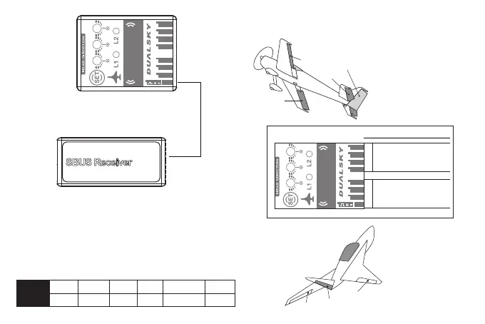
● Input signal supports Futaba S.BUS and S.BUS2, only need
single-signal wire to connect SYS and receivers’ SBUS port.
SYS port has higher priority than other input ports. When using
SYS port, other input ports won’t work, transmitter channel
sequence must be the same as following chart:
Sequence
Channel
CH1
Aileron 1 Elevator
CH2
Throttle
CH3
Rudder
CH4
Mode Switch
CH5
Aileron 2
CH6
3.FC120 corresponding control surface
● Normal type airplane with single or double ailerons
E/R/A2
SYS
AIL1
MODE
AIL2
RUD
AIL1
ELE
FC120
3-axis Flight Control
AIL ELE RUD
N
R
N
R N
R
OUTPUTINPUT
Normal Airplane
PIN (Socket) Location
Aileron
Elevator
Rudder
Aileron 2
TOP MIDDLE BOTTOM
VDD
VDD
VDD
VDD
GND
GND
GND
GND
VDD
VDD
VDD
GND
GND
GND
Switch
Aileron
Elevator
S.BUS
Rudder Aileron 2
* VDD is positive lead. *GND is negative lead.
* Diagram show double aileron airplane
● Fly-wing(delta-wing)
S.BUS Receiver
SBUS
Rudder
Elevator
Aileron2
Aileron
Rudder
Aileron
Elevator