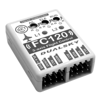
The Dualsky FC120 is an advanced flight control system designed for electric-powered airplanes and unpowered gliders. This sophisticated gyro system integrates a MEMS gyroscope, a 32-bit ARM MCU, and Dualsky's original flight control algorithm to provide precise and stable flight control. Its compact size and user-friendly interface make it a versatile option for various aircraft models.
Function Description:
The FC120 serves as a 3-axis flight control system, primarily enhancing the stability and control of fixed-wing aircraft. It takes over all control channels except throttle, providing stabilization for aileron (roll), elevator (pitch), and rudder (yaw). The system offers both "Gyro Off" mode, where it directly outputs the receiver's signal, and "Aerobatic Mode," where the 3-axis gyroscope actively stabilizes the aircraft.
Key functionalities include:
- Flight Stabilization: Provides active stabilization across three axes (roll, pitch, yaw) in Aerobatic Mode, counteracting external disturbances and improving flight stability.
- Mode Switching: Allows users to switch between "Gyro Off" and "Aerobatic Mode" during flight using a dedicated channel on the transmitter (typically the GEAR channel). If a 5th channel is not available, the FC120 defaults to Aerobatic Mode.
- Sensitivity Adjustment: Features independent sensitivity adjustment for all three axes (aileron, elevator, rudder) via three pots on the device. This allows pilots to fine-tune the gyro's response to their preference and aircraft characteristics.
- Correction Direction Reversal: The pots also allow reversing the correction direction for each axis, ensuring that the control surfaces move correctly to counteract unwanted rotations.
- Flaperon Mixing: Supports flaperon mixing, which allows the ailerons to function as both ailerons and flaps, enhancing the aircraft's versatility.
- Aircraft Type Support: Compatible with various aircraft configurations, including single aileron, double aileron, fly wing (delta-wing), and V-tail aircraft.
- S.BUS Protocol Support: Supports Futaba S.BUS and S.BUS2 protocols, simplifying wiring with a single-signal wire connection to the receiver's SBUS port.
- Programmable via Button and LEDs: The device can be configured using a single "SET" button and two LEDs (L1 and L2), which indicate setting items and values, respectively.
Important Technical Specifications:
- Dimensions: Mini dimension, integrating MEMS gyroscope and accelerometer in one chip.
- Weight: Only 8 grams, minimizing impact on aircraft weight.
- Processor: 32-bit high-performance ARM MCU, ensuring fast and accurate processing of flight data.
- Input Voltage: Supports 4.8V-8.4V voltage input, sharing power with the receiver. Power can be supplied by a battery or ESC.
- Start-up Time: Requires 2-3 seconds for start-up after power-on.
- Mode Switch Pulse Width Range: Low range: 800-1700us (Gyro Off Mode); High range: 1700-2200us (Aerobatic Mode).
- LED Indicators:
- LED1 (Green/Red): Indicates initialization status (flashing green for initializing, solid green for initialization complete/signal OK, solid red for initialization complete/no signal).
- LED2 (Blue/Green): Indicates current flight mode (blue for 0.5s for Gyro Off Mode, green for 0.5s for Aerobatic Mode).
Usage Features:
- Installation Principles:
- Must be mounted with its heading direction aligned with the airplane's heading.
- Must be parallel to the flight path to prevent yaw.
- Should be installed inside the airplane, close to the receiver and center of gravity (CG).
- Installation platform must be solid (plywood recommended) and parallel to the horizontal tail, not a servo mount platform.
- Fixed using the accessory double-sided tape; straps, patches, or 3M Dual-Lock are not recommended.
- Should not be wrapped in foam.
- Must not be touched by servo horns, linkages, or other movable parts.
- Must be kept away from motors, engines, ESCs, and batteries.
- Cannot be installed outside the airplane (e.g., on wings or tail).
- Receiver Connection: Connects to a normal receiver using multiple signal wires or to an S.BUS receiver with a single signal wire to the SYS port. Input/output signal wires have VDD (positive) in the middle and GND (negative) at the bottom.
- Transmitter Requirements: Requires at least a 4-channel transmitter. A 5-channel transmitter is recommended to use the 5th channel (GEAR) for mode switching.
- Ground Test: Before the first flight, perform a ground test to verify mode switch functionality and gyro correction directions. Rotate the model on each axis and observe if the corresponding control surfaces move to counteract the rotation. If incorrect, reverse the pot for that axis.
- Gain Adjustment: Gains for aileron, elevator, and rudder are adjusted via three pots. It's recommended to start with conservative (low) gains and perform test flights to determine appropriate settings. Adjustments should be made in small increments (5-10 degrees at a time) to avoid oscillation at maximum speed.
- Trim System: Initial trimming should be done in "Gyro Off" mode using the transmitter. If transmitter trim is excessive, zero the trim and adjust the model by changing the length of the linkage between the servo arm and the control horn. Trimming is not needed in Aerobatic Mode if the "Gyro Off" mode trimming is complete.
- Setting Mode:
- Entering Setting Mode: Turn on the transmitter, move throttle to minimum, power on the model, wait for L1 green LED to stop flashing, then long-press the "SET" button (2 seconds).
- Navigating Settings: Single click "SET" to switch between setting items (L1 displays item).
- Changing Values: Double click "SET" (within 0.5 seconds) to change setting values (L2 displays value).
- Saving and Exiting: Long-press "SET" in Setting Mode to save changes and exit to flight mode.
- Setting Items:
- Install Direction (L1 Blue): Configures the FC120's mounting orientation (Face up, Face down, Face right, Face left).
- Airplane Type (L1 Green): Selects the aircraft configuration (Normal, Delta wing, V-tail).
Maintenance Features:
- Firmware Updates: While not explicitly detailed in the provided excerpt, advanced flight controllers typically support firmware updates to introduce new features or improve performance.
- Troubleshooting: The LED status indicators provide basic diagnostic information, helping users identify issues like initialization status, signal reception, and current operating mode.
- Physical Inspection: Regular inspection of the FC120's mounting, wiring, and connections is crucial to ensure reliable operation and prevent damage. Ensure it remains free from contact with moving parts and away from heat/EMI sources.
The Dualsky FC120 is a comprehensive flight control solution designed to enhance the flying experience for RC aircraft enthusiasts, offering stability, versatility, and ease of configuration.