2
Start-up of the thermostat
The thermostat can be turned on after wiring connections are complete and tested. To turn the 720 thermostat ON/OFF press the middle button
[Button ] for not less than 3 seconds.
Turning ON/OFF is accompanied by an appropriate animation on the display. After the 720 thermostat is turned on the basic indication appears
on the highlighted display.
Controls and display
Function
The 720 thermostat is designed for the control of electrical underfloor heating systems (heating mats or cable units) or other electrical indoor
heating systems. It automatically maintains a specified temperature exactly when you need it. There is no need to think about your heating man-
agement. You will never have to remember to turn it on. You only need to set the time when you need it, and the 720 thermostat will turn the heat
on for you so far in advance that the required temperature will be achieved by the time you specify. The 720 thermostat is an intelligent and self-
developing system. Its operation is based on its particular experience of heating your house, so it strives every time to execute your commands
more and more precisely and efficiently. The thermostat is equipped with a large highlighted LCD-Display with extended indication that makes it
very easy to use the device. 3 multifunctional control buttons are located under the display; a help string appears in the bottom part of the display
which indicates the current function of the buttons.
The highlight appears when pressing any button and turns off automatically 40 seconds after the last button is pressed. The 720 thermostat
controls the temperature based upon data received from the floor temperature sensor (included in the package). The device displays two tem-
peratures — the actual floor temperature and the « set by you» temperature.
The display also shows the maintenance mode (continuous, daily or weekly schedule). In the bottom part of the display the current day and time
are displayed. The device has self-diagnostics, and will display warning messages. You can set a limit of maximum floor temperature. The device
will also show energy saving statistics per day, per week or per month in the form of a percentage figure.
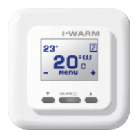
Display
Buttons
The larger numbers (20°C) indicate the actual
floor temperature, the figures in the upper left
corner (23°C) show the floor temperature to
be maintained (the «comfort» temperature),
the sign in the upper right corner indicates the
continuous temperature maintenance mode.
This symbol informs you about the
operation status of the heating system (the
heating is powered when the symbol is
visible).
In the bottom indicator the current functions of
the buttons are shown:
– lowering of the preset temperature,
MENU enter into device's menu,
+ increasing of the preset temperature
1 Current floor temperature (°C)
2 Preset floor temperature (°C)
3 Heating system is powered on
4 Operating mode symbol
5 + button for maintaining temperature increase
6 Button for device turn ON/OFF and menu functions
7 – button for maintaining temperature decrease
When the 720 thermostat is turned on for the first time it starts working in the maintenance mode (factory setting +25°C). When turned on, with
your selected settings, the 720 thermostat starts working in that mode and will retain those parameters until you change them.
You can change the preset floor temperature by pressing for increasing and for reducing. This value will remain set, as the comfort
temperature in all the modes, until you change it again. To activate the device press, and hold, any button. The buttons are not active, i.e. their
first button pressed only «wakes up» the device and turns on the highlighting.
Menu structure of the thermostat
To control the device, and the setting of its working parameters, the thermostat is provided with a graphic menu, subdivided into parts according to
their purpose of function. To enter the menu, press the Menu button in the main indication window of the thermostat.
The name of menu subdivisions will be displayed.
The subdivisions can be browsed by pressing the and the buttons, in the following sequence:
To enter the required menu subdivision, press the button in this division. To return to the main menu press the button in the
Save settings and exit division.
7
Warranty
During the warranty period the customer has the right to get the product repaired or replaced due to faulty materials from the manufacturer on the
condition that the manual guides to Installation and Operation of this device have been followed. The warranty policy does not cover thermostats
with mechanical damage and in cases where the failure is a result of disregard for operating conditions provided in this Manual, and/or instruc-
tions provided for device installation and electrical connections.
Reclamations :In case of failure during the warranty period of the device the customer must immediately apply to the Manufacturer service center
or to the regional authorized representative.
Appendix
Delivery set
720 Thermostat
Floor mounting temperature sensor with connection
cable (2 m)
External terminal block for grounding line connection
User- and installation manual
Packing box
720 thermostat installation manual
* Important: Switch off the power before connecting or disconnecting wiring to the thermostat. A qualified electrician trained to current Indoor
Electrical Equipment regulations must install all wiring. We strongly recommend that you NOT to install the thermostat in premises with high air
humidity. It is prohibited to install the device in bathrooms, saunas, shower cubicles or pools. The thermostat controlling heating in these premises
must be installed in a neighbouring “dry room”.
Please study this manual carefully before starting the installation.
Tools and materials required for thermostat installation:
- Corrugated plastic tube not less than 16mm in diameter; the length depends on the distance between the thermostat and the heating
unit
- Standard junction box for wall mounting units
- Screwdriver
- Phase voltage indicator
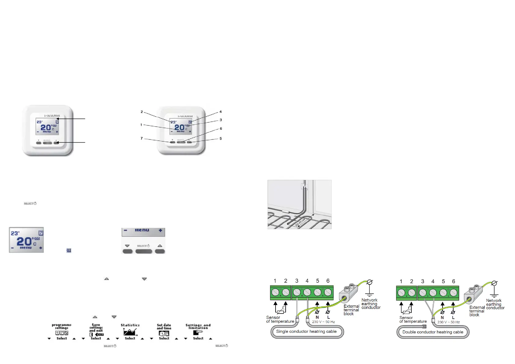
The floor temperature sensor is installed when you perform your heating element (mat or cable section)
installation. The Sensor is connected to the thermostat via a junction box. Place the sensor in the
corrugated plastic tube near its end, and seal this end of the tube to prevent penetration of water, tile
fixing mixture or cement mortar during the installation of the heating system.
The tube containing the temperature sensor must be located at the same level as the heating cable
between two neighbouring passes of this cable. Place the tube in a prepared groove in the floor and
lead its other end to the place chosen for the thermostat or junction box location.
Installation of floor-mounting temperature sensor
Thermostat installation
Preparation of electrical connections
Install the plastic junction box into the wall where the location of the thermostat is planned. Lead the power supply cable, the cold leads of the
heating mat or section, and the temperature sensor cable, into the box.
Connection diagram
 Loading...