8
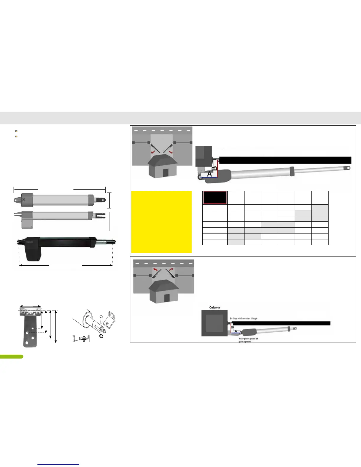
DUCATI actuator model HC312 Installation diagram
HC312
HC312 FC (with on board open position mechanical
limit)
each model is also available in 24V version
METRIC CONVERSION
1 cm = 1⁄2
”
= 0,3
”
10 cm = 4
”
12 cm = 4
3⁄4
”
= 4,7
”
14 cm = 5
1⁄2”
= 5,5“
16 cm = 6
1⁄5”
= 6,2
”
18 cm = 7
”
20 cm = 7
7/8”
= 7,87
”
25 cm = 9
3/4"
= 9,8
”
30cm = 11
8/9”
= 11,8
”
OUTSIDE
INSIDE
PUSH TO OPEN OPERATION (opens towards outside)
If your driveway slopes up after the gate, preventing it from swin-
ging in. This means the gate operator is mounted on the inside
of the property and pushes your gate out away from the property.
Warning: only compatible with telescopic tube actuators, Check
the overall dimensions before installation.
Warning:remember to reverse the polarity of the motor cables
when connecting to the electronic board
A = min. 8cm max. 14cm
B = min. 8cm max. 14cm
PULL TO OPEN OPERATION ( opens towards inside)
This means the gate operator is mounted on the inside of the property
and pulls your gate in towards the property to open.
OUTSIDE
INSIDE
Rear pivot point of gate opener
In line with center hinge
Maximal wing dimension:
Maximal wing lenght: up to 2,5m/ 8 ft
Maximal wing weight: up to 250kg/ 500lb
100
mm
160
mm
620÷920 mm
maximal
dimension
A=8 cm A=10 cmA=12 cmA=14 cm A=18 cmA=20 cm
B=8 cm 98° 110° 118° 125° 108° 100°
B= 10cm 97° 108° 115° 120° 100° 94°
B= 12cm 95° 105° 112° 110° 100° 93°
B= 14cm 95° 103° 109° 98° / /
B= 16cm 94° 101° 97° 90° / /
B= 18cm 94° 97° / / / /
B= 20cm 93° / / / / /
620 -920 mm
Supplied xing braket:
choose the hole most suitable to your gate. you
can cut the plate if necessary
D= 9 cm
D= 11cm
D= 13cm
D= 15,5 cm
10cm
Post xing
Front xing
 Loading...